I/O Mapping Matrix
Purpose
Since v.1.9.0 for devices of WB-MR series and WB-MWAC firmware supports matrix of displaying values of inputs on values of outputs. This additional functionality allows you to flexibly adjust the response of specific outputs of the device depending on the state of its inputs.
Device and operating principle of the mapping matrix
The matrix of actions on outputs for changing input states (mapping matrix) is located in the storage registers of the device, starting from the address 384, and contains 64 registers at the rate of 8 inputs / 8 outputs. Each register contains one of the numeric values that encode the interaction of one of the inputs with one of the outputs.
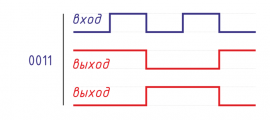
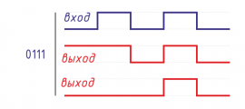
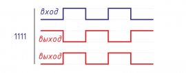
The rows describe the actions when the corresponding input is changed, the columns describe the corresponding outputs. Therefore, the cell at the intersection of the entry date and the exit column contains a value that specifies the operation of the exit when the corresponding entry is changed. The action is described by the value of the lower four bits of the hex word 0b0000 0000 0000 yyxx stored in the register. The yy bits describe the changing of input value from 0 to 1 (front), and the xx bits describe the changing from 1 to 0 (back).
Each combination of two bits describes four possible actions:
- 00 — idle
- 01 — turn off
- 10 — turn on
- 11 — invert value
Thus, it is possible to program the response of each output to the closure and disconnection of any inputs.
Register mapping matrix
| The registers | Outputs | ||||||||
|---|---|---|---|---|---|---|---|---|---|
| 1 | 2 | 3 | 4 | 5 | 6 | 7 | 8 | ||
| Входы | 1 | 384 | 385 | 386 | 387 | 388 | 389 | 390 | 391 |
| 2 | 392 | 393 | 394 | 395 | 396 | 397 | 398 | 399 | |
| 3 | 400 | 401 | 402 | 403 | 404 | 405 | 406 | 407 | |
| 4 | 408 | 409 | 410 | 411 | 412 | 413 | 414 | 415 | |
| 5 | 416 | 417 | 418 | 419 | 420 | 421 | 422 | 423 | |
| 6 | 424 | 425 | 426 | 427 | 428 | 429 | 430 | 431 | |
| 7 | 432 | 433 | 434 | 435 | 436 | 437 | 438 | 439 | |
| 0 | 440 | 441 | 442 | 443 | 444 | 445 | 446 | 447 | |
The previous version of the configuration interaction of the inputs and outputs of relay modules
The new firmware also retained the mechanism for managing input-output links from previous firmware versions. Holding-register 5 describes the behavior of all inputs, and registers 9 to 9+x-1 (x — the number of relays in the module) and register 16 (zero input) — the behavior of each individual input.
Registers can contain the following control values:
| The value of the register | Operation mode inputs | Note |
|---|---|---|
| 0 | Buttons without locking | |
| 1 | latching Switch | |
| 2 | Disable all relays when pressing | with firmware 1.9.0 |
| on| Disable interaction of inputs and outputs | ||
| 4 | Manage according to the Mapping matrix | with firmware v.1.9.0 |
| 5 | Control according to the Mapping matrix, after 20 minutes re-simulate the input state |
with firmware v.1.9.0 |
Setting the control mode of individual inputs is possible only if the value 0 is written in the holding register 5. In the latest firmware in the factory supply, all input mode registers contain 0, except for register 16 — it contains the value 2, which ensures the operation of the input 0 as "emergency" — when you press the button without fixing, connected to this input, all relays will turn off. Pressing it again will leave the relay is off.
Re-simulation of the input state after 20 minutes (mode 5) means that every 20 minutes an action will be performed on the output (according to the matrix), as if the input has just changed the state: if the input is closed, then the action is performed on the rising edge. If open — the on the back. This mode provides additional reliability when controlling the relay leakage sensors connected to the inputs. The following scenario is worked out: when the inlet is closed by the leakage sensor, the ball valve closes the water. At some point, the command to open the crane (for example, Modbus) comes. But, if the leak is still fixed by the sensor, after 20 minutes the tap will be closed again.
= The programming examples of the interaction of inputs and outputs
Let's consider some examples of programming the interaction of inputs and outputs on the example of relay module WB-MR6C with firmware 1.9.4. The module has 7 dry contact inputs and 6 relay outputs. The default input 0 is used to disable all relay modules and the buttons 1 to 6 are used to control relay modules.
In the examples, we focus on the factory settings of the communication parameters of the module, Modbus-address — 1. The module is connected to the first port of the Wiren Board 6 controller.
All examples are executed when the wb-mqtt-serial driver is stopped:
service wb-mqtt-serial stop
Switches with locking
Write in register 5 value 1:
modbus_client --debug -mrtu -pnone -s2 /dev/ttyRS485-1 -a1 -t0x06 -r5 1
Now all inputs of the module function as inputs for switches with fixation. Disadvantage: Input 0 stops functioning.
To save the "emergency" input mode 0 return to register 5 value 0, and in the registers 9, 10, 11, 12, 13, 14 write 1:
modbus_client --debug -mrtu -pnone -s2 /dev/ttyRS485-1 -a1 -t0x06 -r5 0
modbus_client --debug -mrtu -pnone -s2 /dev/ttyRS485-1 -a1 -t0x10 -r9 1 1 1 1 1 1
Now all inputs operate in switch mode with locking, and a short press on the button connected to input 0 will turn off all relays.
Disable input / relay communication
To disable the interaction of inputs and relays (for example, if we want to control the relay only through the controller rules engine), write the value 0 in register 5, and in registers 9, 10, 11, 12, 13, 14 write the value 3:
modbus_client --debug -mrtu -pnone -s2 /dev/ttyRS485-1 -a1 -t0x06 -r5 0
modbus_client --debug -mrtu -pnone -s2 /dev/ttyRS485-1 -a1 -t0x10 -r9 3 3 3 3 3 3
Now clicking on the button or toggle switch will change the relay status you can manage only programmatically via Modbus. In this case, the function of the emergency input 0 is saved: a short press on the button connected to the input 0 will turn off all the relays.
If we want to disable and input 0, then write the value 3 in register 16:
modbus_client --debug -mrtu -pnone -s2 /dev/ttyRS485-1 -a1 -t0x06 -r16 3
Using the Mapping matrix
More complex scenarios of interaction between inputs and relays can be implemented using a Mapping matrix. To use the Mapping matrix, write the value 0 in the holding register 5:
modbus_client --debug -mrtu -pnone -s2 /dev/ttyRS485-1 -a1 -t0x06 -r5 4
And registers the settings of the interaction of inputs/outputs — value 4:
modbus_client --debug -mrtu -pnone -s2 /dev/ttyRS485-1 -a1 -t0x10 -r 9 4 4 4 4 4 4
modbus_client --debug -mrtu -pnone -s2 /dev/ttyRS485-1 -a1 -t0x06 -r16 4
Mapping mapping-the matrix is filled with zeros. If you are unsure and want to erase the entire matrix, write 0 in each of the 64 holding registers starting with 384:
modbus_client --debug -mrtu -pnone -s2 /dev/ttyRS485-1 -a1 -t0x10 -r384 $(printf ' 0%.0s' {1..64})
Input 0 turns all relays on and off
Program the matrix in such a way that the input 0, working in the mode of the button (switch without fixation), sequentially turns on and off all the relays of the module when closed.
To do this, we turn to the register map of the mapping matrix and see that the input 0 corresponds to the registers 440 — 447. And for interaction with inputs 1 — 6 registers 440 — 445 are responsible.
We want the input to work as a switch without locking and triggered when pressed (on the rising edge), and when opened, nothing would happen. The state of all relays must be inverted each time they are pressed. This corresponds to a combination of 11 00: (12, 0x0C) — Change the output state when shorted:

Write in the registers 440 — 445 the value of 12:
modbus_client --debug -mrtu -pnone -s2 /dev/ttyRS485-1 -a1 -t0x10 -r440 12 12 12 12 12 12
Let's check the operation: at the first circuit of input 0 all relays are switched on, at the second — all relays are switched off.
= = = = Inverted switch with locking ==
Set up the inputs so that when closed inputs relay would be disabled, and open -- is included.
For this closing input (rising edge) the corresponding output shall be switched off (01), and upon opening the entrance (back front) — included (10). This corresponds to the value 6: 
In the matrix, the desired interaction registers input 1 — output 1, input 2 — output 2, etc. are located diagonally. These are registers 384, 393, 402, 411, 420, 429. They need to write the value 6:
for i in 384 393 402 411 420 429; do modbus_client --debug -mrtu -pnone -s2 /dev/ttyRS485-1 -a1 -t0x06 -r$i 6; done
Note: the relay state changes only when the input state changes.
Leak sensor
Let the leak sensor be connected to the input 1, and the relays 1 and 2 control the ball valve actuators. Relay 3 controls the warning lamp or buzzer. When wetting the leakage sensor relay 1 and relay 2 are closed and the actuators close the ball valves. Relay 3 closes and switches on the buzzer. Input 2 will be programmed to reset the alarm and open the ball valves.
Clear the mapping matrix:
modbus_client --debug -mrtu -pnone -s2 /dev/ttyRS485-1 -a1 -t0x10 -r384 $(printf ' 0%.0s' {1..64})
Apply in our case, the mode when the input state is repeated every 20 minutes, for this write in the register 9 value 5 (control in accordance with the mapping matrix, after 20 minutes to re-simulate the input state), and the rest — the value 4 (control in accordance with the mapping matrix).
modbus_client --debug -mrtu -pnone -s2 /dev/ttyRS485-1 -a1 -t0x10 -r9 5 4 4 4 4 4
To enter the leakage sensor (input 1) use the mode 1000 (8) — turn on when the circuit. 
To enter the reset button (input 2) use mode 0100 (4) — turn off when closing. 
On the map mapping-registers we determine that to enter 1, you need to write the value 8 in the registers 384, 385, 386, and to enter 2 — write the value 4 in the registers 392, 393, 394:
modbus_client --debug -mrtu -pnone -s2 /dev/ttyRS485-1 -a1 -t0x10 -r384 8 8 8
modbus_client --debug -mrtu -pnone -s2 /dev/ttyRS485-1 -a1 -t0x10 -r392 4 4 4
Checking: close input 1 and iGND and leave it closed. Relays 1, 2 and 3 must be switched on. Then we close and open the input 2 — all three relay relays are off. Wait 20 minutes. Since input 1 remains closed (leakage is not eliminated), relays 1, 2 and 3 will switch back on after 20 minutes.
Leaving input 1 closed, turn off and turn on the relay power: after 20 minutes, relays 1, 2 and 3 will turn on again.


