WB-MR3xV and WB-MR6xV Modbus Relay Modules english
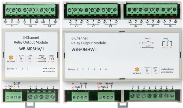
Three or six channels relay modules of the WB-MR3xV and WB-MR6xV series can be used in industrial and home automation systems. Different modifications of the relay modules are targeted for switching general purpose devices, including inductive and capacitive load: the modules can be used to switch LED lightning fixtures, incandescent lamps, pulse power supply units and so on.
The maximum switching current for all the modules is 16A (the rated switching current is 10A). No additional power couple relays are needed. All the modules have special input which turns off all the relays at once.
Models
The WB-MR3xV modification provides three switching channels while the WB-MR6xV provides six switching channels. The modules have dry contact or 230V AC inputs. Different relay types are used in modules for switching different types of load.
Naming scheme:
| 6]xV | N | XX | / | YY | |||
|---|---|---|---|---|---|---|---|
| Channels | 'Input type | Relay output type | |||||
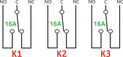
| 3 or 6 | LV | dry contact inputs (Low Voltage) | I | (SPDT, single-pole double-throw, NO/NC contacts), large inrush current (I) | |||
| HV | 230V AC inputs (High Voltage) | S | SPST (single pole/single throw, NO contact), extra large inrush current, with tungsten-enforced contacts (S -- Special model) | ||||
| R | (SPDT, single-pole double-throw, NO/NC contacts), modules for resistive load (R) (could be purchased only on a by-order basis) | ||||||
Outputs
Several relay types are used in modules of different modifications. The following table contains the description of relay models, their specifications and usage cases. Maximum allowable DC voltage for all the modules is 30 V. Each relay contact is protected from arching while circuit switching by variable resistors connected to the common "С" contact. The state of the module relays may be restored after power outage, if it is set on in the corresponding Modbus-register (see the #Power outage behaviour chapter).
Relay specifications
| I model | S model | R model | |
|---|---|---|---|
| Peak switching current,
resistive load 230V AC |
16А | ||
| Peak switching current,
resistive load 30V DC |
- | - | 16A |
| Maximum switching power
for incandescent bulbs (230V AC) |
3000W | ||
| Peak inrush current
(during 20ms, for the NO contact) |
120A | 165A | - |
| Peak inrush current
(during 200 us, for the NO contact) |
- | 800A | - |
| Contact resistance | 100 mOhm | ||
| Contact material | AgSnO2 | W+AgSnO2 | AgSnO2 |
| Contact configuration | SPDT (NO, COM, NC) | SPST (NO, COM) | SPDT (NO, COM, NC) |
| Life cycle: number of switching events
for the 16A 230V AC, cos φ = 1 load |
75 000 | 12 000 | 30 000 |
| Life cyle: number of switching events
without load |
10 000 000 | 5 000 000 | 20 000 000 |
| Relay model | Hongfa HF115F-I | Hongfa HF115F-S | Omron G2RL-1-E |
| Special features | Large inrush current,
switched contact set |
Extra large inrush current | Low price |
| Usage cases | General purpose devices, inductive and capacitive load. Electric motors, coupling relays, incandescent bulbs,
LED light fixtures, pulse power supplies and so on. |
Resistive load, coupling relays,
inductive and capacitive load of low power. | |
Inputs
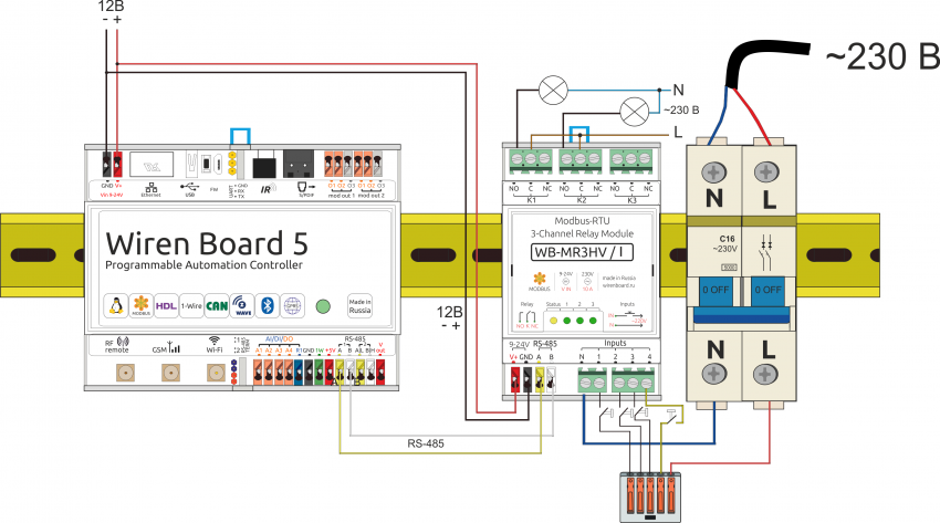
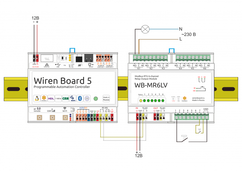
Inputs of the WB-MR3xV and WB-MR6xV modules are connected to the screw terminals. The purpose of input types varies, based on the module type. The LV-modification has dry contact inputs. Buttons or switches should be connected to the GND and the appropriate input. The HV-modification inputs sense the 230V AC voltage. The pickup voltage for these inputs is between 90 — 250 VAC. External buttons and switches are connected to the phase (L) wire and the appropriate input. The neutral wire (N) of the 230 VAC mains should be connected to the "N" terminal of the module.
Specification
| Parameter | Value |
|---|---|
| Power supply | |
| Power supply | 9 — 24 VDC |
| Watt consumption |
|
| 'Outputs | |
| Output type | Electromagnetic relay contacts |
| Output configuration | 3 оr 6 outputs connected to the relay contacts |
| Contact configuration for each output | Two-stage normally opened for S model (С and NO)
Two-stage normally opened with switching for I and R models (NC C NO) |
| Maximum switching voltage, AC | 250 V |
| Maximum switching voltage, DC | 30 V |
| Maximum switching current, per channel |
see the table in the #Relay specifications chapter |
| Contact resistance | less than 100 mOhm |
| Insulating voltage between the module and the output | 1500 V (RMS) |
| Life cycle: | see table in the #Relay specifications chapter |
| Inputs | |
| Number of inputs (Inputs 1—4) | 4 (3+1) in WB-MR3xV
7 (6+1) in WB-MR6xV |
| Input type (WB-MR3LV and WB-MR6LV) | Dry contact, group insulation.
Input voltage ~4,5V. Vinput short current ~2 ma. |
| Input type (WB-MR3HV and WB-MR6HV) | Mains presence, group insulation.
Inputs pickup voltage: 90В — 250VAC/DC. Current ~0,5 ma. |
| Usage |
|
| Control | |
| Control interface | RS-485 |
| Interface insulation | Non insulated |
| Communication protocol | Modbus RTU with programmatically set address, factory settings are printed on the sticker |
| RS-485 interface parameters | set programmatically (see the Modbus control) chapter; default settings: data rate — 9600 bps; data — 8 bit; parity bit — none (N); stop bits — 2 |
| Operational readiness after power-up | ~0,03 sec |
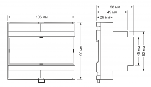
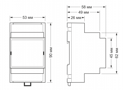
| External dimensions | |
| Width (DIN-units) | 3 |
| Geometry (Length x Width х Height) | WB-MR3xV: 53.3 x 90.2 x 57.5 mm
WB-MR6xV: 106.25 x 90.2 x 57.5 mm |
| Indicators | |
| Power and communication | Yellow Status LED |
| Relay channel state | Green LEDs, WB-MR3xV: 1 — 3, WB-MR6xV: 1 — 6 |
| Environmental conditions | |
| Ambient temperature | From -40 to +50 °С |
| Relative humidity | Up to 92%, non-condensing |
Modules external dimensions
WB-MR3xV and WB-MR6xV modules installation
The relay modules should be installed on the standard 35-mm DIN-rail. Module width is 3 or 6 DIN-units.
WWAGO screwless terminals are used to connect power and control (RS-485) lines, as well as input contacts. When using insulated wire ferrules to connect wires to the screwless terminals please keep in mind that the diameter of the insulation cap should not exceed 3.6 mm, the wire cross-section should not exceed 0.75 mm2, and the length of the conductive part of the ferrule should not be longer than 5—6 mm. Wires with cross-section 2.5—4 mm2 can be connected to the screw terminals of the module. The wire cross-section should correspond to the connected switching load.
Do not exceed the rate current of 16 А on Kx relay contacts
You can choose any appropriate type button or switch to connect to the inputs, as far as the short current is not large. Despite of the debouncing circuit of the module, please choose high grade buttons or switches to eliminate false response.
WARNING! High voltage may be presented at terminals of the HV modules!
You should connect terminating resistor of about 120 Ohms to the A and B terminals of the last device on the RS-485 line. The terminating resistor is not required on short lines and low bps speeds.
The module should be installed in such a way to satisfy the ESR and prevent touching terminals where the high voltage may present. The relay modules should operate under recommended environmental conditions.
Power outage behaviour
The 0x06 Modbus holding register changes the relay state maintenance after power outages: value of 0 means that all the relays stay in the off state after the power appears, 1 means that all the relays previously switched on will be switched on again). This works in modules with firmware 1.5.3 or later.
Modbus control
See the Управление модулями реле Wirenboard по протоколу Modbus page on Modbus control of the relay modules. The you can also find the register map of the devices.
