Участник:EvgenyBoger/CT309-test/en: различия между версиями
(Новая страница: «The assembly is intended for use in conjunction with WB-MAP meters as a replacement for split transformers. The use of one-piece transformers is often more convenient and reliable when assembling the shield from scratch.») |
FuzzyBot (обсуждение | вклад) (Обновление для соответствия новой версии исходной страницы.) |
||
| (не показано 14 промежуточных версий 2 участников) | |||
| Строка 1: | Строка 1: | ||
<languages/> | <languages/> | ||
<div lang="ru" dir="ltr" class="mw-content-ltr"> | |||
{{DISPLAYTITLE: Сборка неразъемных трансформаторов WB-CT309}} | {{DISPLAYTITLE: Сборка неразъемных трансформаторов WB-CT309}} | ||
</div> | |||
{{PDF}} | {{PDF}} | ||
| Строка 10: | Строка 11: | ||
The assembly is intended for use in conjunction with WB-MAP meters as a replacement for split transformers. The use of one-piece transformers is often more convenient and reliable when assembling the shield from scratch. | The assembly is intended for use in conjunction with WB-MAP meters as a replacement for split transformers. The use of one-piece transformers is often more convenient and reliable when assembling the shield from scratch. | ||
<div lang="ru" dir="ltr" class="mw-content-ltr"> | <div lang="ru" dir="ltr" class="mw-content-ltr"> | ||
Смотрите также статью [[RS-485:Физическое_подключение]]. | |||
</div> | </div> | ||
== Specifications== | |||
[[File:ErorrZMCT123.png|300px|thumb|right| | |||
[[File:ErorrZMCT123.png|300px|thumb|right|Transformer current measurement error]] | |||
{| class="wikitable" style="clear:none" | {| class="wikitable" style="clear:none" | ||
! style="text-align: center;" | | ! style="text-align: center;" | Parameter | ||
! style="text-align: center;" | | ! style="text-align: center;" | Value | ||
|- | |- | ||
| | |Rated current | ||
| 5 | | 5 A | ||
|- | |- | ||
| | |Maximum current | ||
| 125 | | 125 A | ||
|- | |- | ||
| | |Hole diameter (max. cable diameter) || 9.5 mm | ||
|- | |- | ||
| | |Transformation ratio || 1:2000 | ||
|- | |- | ||
| | |Phase angle, 1/1000 of a degree || 120 | ||
|- | |- | ||
| | |Dimensions (L x W x H)|| 74 x 30 x 36 mm | ||
|- | |- | ||
{{Участник:EvgenyBoger/Wbincludes:Weight}} | |||
{{Wbincludes:Weight}} | 70 g | ||
70 | |||
|} | |} | ||
Datasheet for used transformers: [[File:ZMCT123.pdf|File:ZMCT123.pdf]] | |||
== Mounting == | |||
= | |||
[[File:Mount_CT.jpg|300px|thumb|right|An example of mounting two assemblies]] | |||
[[File:Mount_CT.jpg|300px|thumb|right| | |||
Step between transformers - 1 DIN module (17.5 mm). It is convenient to install the assembly immediately under the machines. They can also be joined two at a time by turning the right assembly over and crimping the second end of the cable in a different order - this way the step between the transformers will be preserved.! N! It can be attached to the shield panel using self-tapping screws to plastic racks. You can also simply fix it on the cable with ties (put it on the cable itself to limit the stroke). | |||
An adapter with an RJ-12 socket is inserted into the WB-MAP meter instead of a mating terminal block and connected to the transformers with a connecting cable (included). The cable is made of a twisted pair and two 6P6C (RJ-12) plugs crimped in a straight pattern: white-orange, orange, white-green, green, white-blue, blue (see diagram 1). | |||
If you install two transformer assemblies side by side and turn the second one over, then one of the ends of the cable must be crimped according to a different scheme: orange, white-orange, green, white-green, blue, white-blue (see diagram 2). | |||
It is not recommended to work without connection to the WB-MAP meter. | |||
<gallery widths=260px heights=219px style="clear:both"> | <gallery widths=260px heights=219px style="clear:both"> | ||
Image: Installation WB-CT309.png | | Image: Installation WB-CT309.png | Selection of crimping scheme depending on the orientation of the transformer assembly | ||
Image: WBCT_RJ12_pinout.png | | Image: WBCT_RJ12_pinout.png | Scheme 1. Crimping a twisted pair for connecting a transformer assembly. Serial version | ||
Image: WBCT_RJ12_pinout invert.png | | Image: WBCT_RJ12_pinout invert.png | Scheme 2. Crimping a twisted pair for connecting an '''inverted''' transformer assembly | ||
</gallery> | </gallery> | ||
== Known Issues == | |||
= | |||
There are no known faults. | |||
== Device revisions == | |||
= | |||
{{Wbincludes:Revision}} | {{Участник:EvgenyBoger/Wbincludes:Revision/{{PAGELANGUAGE}}}} | ||
|- | |- | ||
|1.4 | |1.4 | ||
| Строка 105: | Строка 77: | ||
|06.2021 - ... | |06.2021 - ... | ||
| | | | ||
* | *Added TVS on secondary | ||
|- | |-! N!|1.3 | ||
|1.3 | |||
|v1.3A - v1.3E | |v1.3A - v1.3E | ||
|03.2021 - 11.2021 | |03.2021 - 11.2021 | ||
| | | | ||
* | *First revision | ||
|- | |- | ||
|} | |} | ||
== Images and drawings of the device == | |||
= | |||
[[File:WBCT-309_drawing.png |350px|thumb|right|Dimensions]] | |||
[[File:WBCT-309_drawing.png |350px|thumb|right| | |||
{{Wbincludes:CDR lib}} | {{Wbincludes:CDR lib}} | ||
'''Corel Draw PDF:''' [[File:CT3.cdr.pdf|File:CT3.cdr.pdf]] | '''Corel Draw PDF:''' [[File:CT3.cdr.pdf|File:CT3.cdr.pdf]] | ||
Текущая версия на 03:25, 21 марта 2022

Purpose
The assembly is intended for use in conjunction with WB-MAP meters as a replacement for split transformers. The use of one-piece transformers is often more convenient and reliable when assembling the shield from scratch.
Смотрите также статью RS-485:Физическое_подключение.
Specifications

| Parameter | Value |
|---|---|
| Rated current | 5 A |
| Maximum current | 125 A |
| Hole diameter (max. cable diameter) | 9.5 mm |
| Transformation ratio | 1:2000 |
| Phase angle, 1/1000 of a degree | 120 |
| Dimensions (L x W x H) | 74 x 30 x 36 mm |
| Масса (с коробкой) |
70 g |
Datasheet for used transformers: Файл:ZMCT123.pdf
Mounting

Step between transformers - 1 DIN module (17.5 mm). It is convenient to install the assembly immediately under the machines. They can also be joined two at a time by turning the right assembly over and crimping the second end of the cable in a different order - this way the step between the transformers will be preserved.! N! It can be attached to the shield panel using self-tapping screws to plastic racks. You can also simply fix it on the cable with ties (put it on the cable itself to limit the stroke).
An adapter with an RJ-12 socket is inserted into the WB-MAP meter instead of a mating terminal block and connected to the transformers with a connecting cable (included). The cable is made of a twisted pair and two 6P6C (RJ-12) plugs crimped in a straight pattern: white-orange, orange, white-green, green, white-blue, blue (see diagram 1).
If you install two transformer assemblies side by side and turn the second one over, then one of the ends of the cable must be crimped according to a different scheme: orange, white-orange, green, white-green, blue, white-blue (see diagram 2).
It is not recommended to work without connection to the WB-MAP meter.
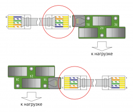
Selection of crimping scheme depending on the orientation of the transformer assembly
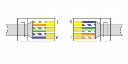
Scheme 1. Crimping a twisted pair for connecting a transformer assembly. Serial version
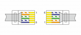
Scheme 2. Crimping a twisted pair for connecting an inverted transformer assembly


Known Issues
There are no known faults.
Device revisions
The batch number (Batch No.) is indicated on a sticker on the side of the case or on the printed circuit board.
| Revision | Games | Release date | Differences from previous revision |
|---|---|---|---|
| 1.4 | v1.4A, v1.4B - ... | 06.2021 - ... |
|
| v1.3A - v1.3E | 03.2021 - 11.2021 |
|
Images and drawings of the device

Corel Draw 2018 (шрифт — Ubuntu): Файл:WB-Library.cdr.zip
Visio:
- Устройства Wiren Board: Файл:WB-Visio-Lib.cdr.zip.
- Щиты, автоматы, контакторы и прочее от стороннего разработчика.
Corel Draw PDF: Файл:CT3.cdr.pdf