Input-output modules
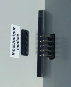
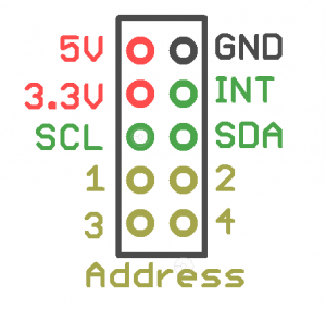
Input and output modules are stacked together with the Wiren Board controller through the connector on the right side of the enclosure.
You can connect up to 8 modules: Up to 4 input modules (type I), and up to 4 output module (Type O and IO). Exception: only one WBIO-AI-DV-12 module can be connected. The module type determines the module address on the side connector bus of the controller.
Addresses are distributed in the order of connection. Up to 4 modules can be connected in any order. With a larger number, you should daisy-chain connect modules of one type first, then of another type.
Communication Interface - I2C.
| Article | Description | Number of channels | Channel type | Width, DIN units rail | Type |
|---|---|---|---|---|---|
| Input modules | |||||
| WBIO-DI-DR-8 | digital dry contact inputs module | 8 | digital dry contact inputs | 2U | I |
| WBIO-DI-DR-16 | digital dry contact inputs module | 16 | digital dry contact inputs | 3U | I |
| WBIO-DI-DR-14 | digital dry contact inputs module | 14 | digital dry contact inputs | 2U | I |
| WBIO-DI-WD-14 | universal digital dry contact inputs module | 14 | digital dry contact inputs
low voltage presence inputs |
2U | I |
| WBIO-DI-HVD-8 | discrete 220V AC voltage presence detection inputs module | 8 | 220V AC voltage presence detection inputs | 2U | I |
| WBIO-DI-HVD-16 | discrete 220V AC voltage presence detection inputs module | 16 | 220V AC voltage presence detection inputs | 3U | I |
| WBIO-DI-LVD-8 | Voltage 12/24 V presence detection module | 8 | discrete 12/24V presence detection inputs | 2U | I |
| WBIO-DI-LVD-16 | Voltage 12/24 V presence detection module | 16 | discrete 12/24V presence detection inputs | 3U | I |
| WBIO-AI-DV-12 | Analog inputs module | 12 (6 diff.) | analog inputs 0-3V,-50..+50V | 3U | I |
| WBIO-AI-DV-12/4-20MA | Analog inputs 4-20mА module | 12 | Analog inputs 4-20mА | 3U | I |
| Output modules | |||||
| WBIO-DO-R3A-8 | relay outputs 3A module | 8 | relay outputs, SPST and SPDT | 3U | O |
| WBIO-DO-R10A-8 | relay outputs 10A module | 8 | relay outputs, SPST | 3U | O |
| WBIO-DO-R10R-4 | relay outputs (roller shutter) 10A module | 4 | relay outputs, SPCO | 3U | O |
| WBIO-DO-R1G-16 | 16 channel relay outputs module for managing contactors | 16 | relay outputs, SPST | 3U | O |
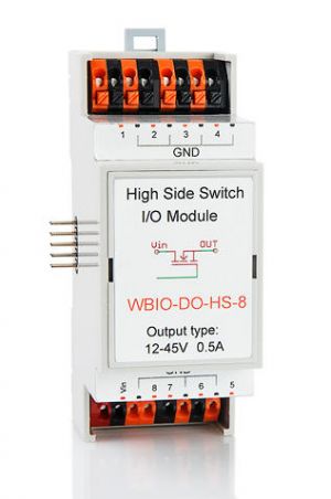
| WBIO-DO-HS-8 | High Side Switch discrete inputs module | 8 | High Side Switch outputs | 2U | O |
| WBIO-DO-SSR-8 | Solid State Relay Output Module for managing low voltage loads | 8 | solid state relays, SPST, up to 40V | 2U | O |
| WBIO-AO-10V-8 | analog outputs module WBIO-AO-10V-8 | 8 | analog outputs 0 to 10 V | 2U | O |
| Input-output modules | |||||
| WBIO-DIO-TTL-8 | TTL inputs and outputs module | 5V TTL GPIO | 2U | O | |
Activating the modules in the controller web interface
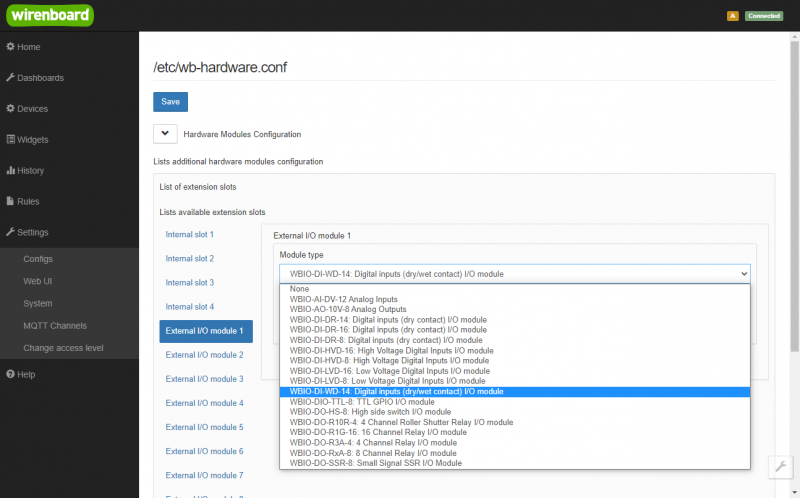
To activate a new module connected to the controller, go to the Hardware Modules Configuration section. Select the module position in the List of extension slots(for example, the first position: External I/O module 1). Select the type in the Module type list.
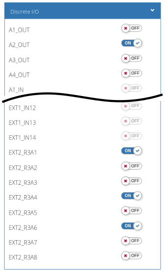
Click the Save button at the top of the page and make sure that the external module is visible in the web interface:
MQTT-topics of the new module: /devices/wb-gpio/controls/EXT1_K1 — /devices/wb-gpio/controls/EXT1_K8
