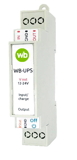
WB-UPS
Uninterruptible power supply module on Li-Ion batteries. Designed to maintain the operation of the controller and connected modules in the absence of supply voltage.
Technical specifications
The module contains a charge circuit Li-Ion battery with charge protection at low and high temperatures. Batteries — two 750 mAh. The charging current is 380 mA, full charge time is ~2.5 hours.
Has two modes - 12/24V mode is selected by the switch
Power supply to Vin is required to turn on. The Input indicator lights up (green/yellow). The input voltage is supplied to the Vout via the diode. If the voltage drops below 11V (22V), the boost Converter from the batteries is activated and maintains this voltage on the Vout. The Output indicator lights up red. To turn off the module, press the OFF button. Power supply to Vin is required to turn on.
| Specifications | |
|---|---|
| Input voltage | 12-28 V |
| Rated power | 12 W |
| Peak power | 15 W |
| Operating time (12 W) | 20 min |
| Power consumption
(when charging) |
3 W |
| Display | |
| Input - solid green | There is input voltage,
batteries charged |
| Input - solid yellow | There is input voltage,
charging in progress |
| Output - solid red | Battery operation. |
| battery parameters | |
| Type of battery | Li-ion LIR14500-PCM |
| Rated voltage | 3.7 V |
| Rated capacity (C) | 2x750 mAh |
| Maximum charge/discharge current | 1.5 A |
| Charging voltage | 4.2 V |
| Operating temperature | Charge: 0°C to 45°C
Discharge: -20°C to 60°C |
| Storage temperature | |
Indicators
The panel has two indicator lights: Input - lights green - batteries are charged, there is an input voltage.
Input - yellow light - is charging the batteries, there is an input voltage.
Output - red light - battery life.
If the Input and Output indicators are lit at the same time, the input voltage is below the battery threshold. For example, the input is 12V and the switch is in 24V mode.
If the power supply is adjustable output voltage - set it above the threshold.
Output Status
In the presence of the input voltage - the Status output is pulled to the ground resistance of 470 Ohms. When working on batteries - the output Status voltage is supplied from the batteries. You can connect both the digital input of the controller and analog, with this voltage on the batteries can be judged on the remaining charge and operating time.
Installation
Note the small allowable temperature range for the module to operate. Operation of the module is possible only in the range of -20°C to 60°C, and the battery is charged at a temperature of 0°C to 45°C. Therefore, use with caution in unheated areas. Do not allow the module to overheat - do not install in the shield close to highly heated components - for example, to contactors. To improve cooling, install from the edge of the shield, insert the lock on the DIN rail between it and the adjacent module.
