WBIO-AI-DCM-4 I/O Module/en: различия между версиями
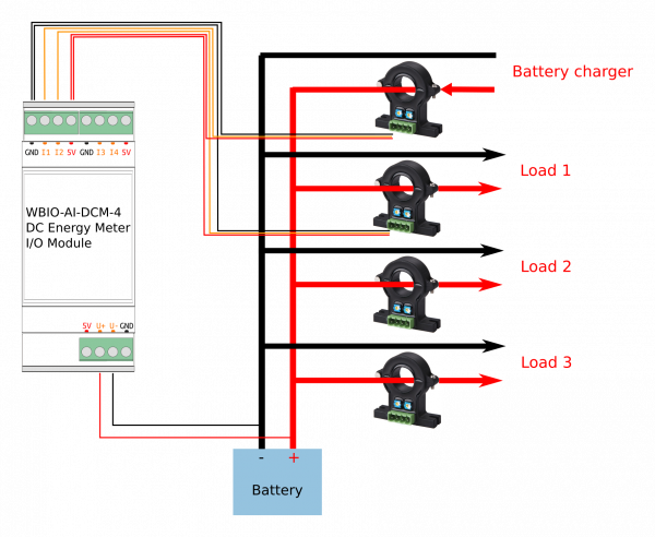
(Новая страница: «== Connection == мини|600x600пкс|WBIO-AI-DCM-4 Wiring») |
(Новая страница: «{| class="wikitable" !Parameter !Value |- ! colspan="2" |voltage measuring Inputs |- | rowspan="2" |Number of inputs |2 (single-ended) |- |1 (differential) |- |In…») |
||
| (не показаны 3 промежуточные версии этого же участника) | |||
| Строка 49: | Строка 49: | ||
5V power supply, | 5V power supply, | ||
выход 2.5V +/- 0.625V (FS) | |||
|- | |- | ||
| | |Допустимое напряжение | ||
| -5V .. +5V | | -5V .. +5V | ||
|- | |- | ||
| | |Выход питания для датчиков Холла | ||
|5V, | |5V, общий для всех датчиков | ||
с защитой от КЗ | |||
|- | |- | ||
! colspan="2" | | ! colspan="2" |Прочее | ||
|- | |- | ||
| | |Тип модуля | ||
|"I" (inverted address scheme) | |"I" (inverted address scheme) | ||
|- | |- | ||
| | |Максимальная потребляемая мощность | ||
|0 | |0,1 Вт | ||
|- | |- | ||
| | |Ширина, DIN юнитов | ||
|2 | |2 | ||
|- | |- | ||
| | |Размер | ||
|36,3x90,2x57,5 | |36,3x90,2x57,5 мм | ||
|} | |} | ||
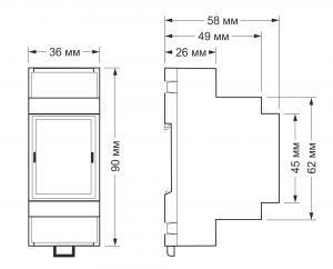
[[File:DIN 2U.png |300px|thumb|right| | [[File:DIN 2U.png |300px|thumb|right|Габаритные размеры]] | ||
== | == Подключение к контроллеру == | ||
Смотрите раздел [[Модули ввода-вывода#Активирование нового модуля в веб-интерфейсе контроллера|Активирование нового модуля в веб-интерфейсе контроллера]] | |||
== | == Подключение == | ||
[[Файл:WBIO-AI-DCM-4 wiring.png|мини|600x600пкс|WBIO-AI-DCM-4 Wiring]] | [[Файл:WBIO-AI-DCM-4 wiring.png|мини|600x600пкс|WBIO-AI-DCM-4 Wiring]] | ||
Версия 20:01, 19 июля 2019
Module is discontinued and replaced by WBIO-AI-DV-12 module
Purpose
The device is designed for tasks that require monitoring of currents and voltages in DC networks, for example for technical metering of electricity.
The device directly measures the voltage and current in the load. The values obtained are used to calculate power (kW) and energy (kWh).
Technical specifications
Contains 4 inputs for Hall sensors for load current measurement and 1 (2) input for voltage measurement.
| Parameter | Value |
|---|---|
| voltage measuring Inputs | |
| Number of inputs | 2 (single-ended) |
| 1 (differential) | |
| Input type | voltage measurement,
uninsulated |
| Measured voltage | 48V DC (0-70V) |
| Allowable voltage | -70V ... +70V DC |
| Input impedance | 10 kOhm |
| current measuring Inputs | |
| Number of inputs | 4 |
| Input type | connecting hall sensors |
| Sensor type | open-loop,
5V power supply, выход 2.5V +/- 0.625V (FS) |
| Допустимое напряжение | -5V .. +5V |
| Выход питания для датчиков Холла | 5V, общий для всех датчиков
с защитой от КЗ |
| Прочее | |
| Тип модуля | "I" (inverted address scheme) |
| Максимальная потребляемая мощность | 0,1 Вт |
| Ширина, DIN юнитов | 2 |
| Размер | 36,3x90,2x57,5 мм |
Подключение к контроллеру
Смотрите раздел Активирование нового модуля в веб-интерфейсе контроллера

