Wiren Board 4:Аппаратная часть/en: различия между версиями
| (не показано 55 промежуточных версий 4 участников) | |||
| Строка 30: | Строка 30: | ||
|| [[Special:MyLanguage/GSM/GPRS|GSM/GPRS]] || 900/1800 МГц. GPRS multi-slot class 10/8 max. 85.6 kbps (downlink). microSIM card, packaged | || [[Special:MyLanguage/GSM/GPRS|GSM/GPRS]] || 900/1800 МГц. GPRS multi-slot class 10/8 max. 85.6 kbps (downlink). microSIM card, packaged | ||
|- | |- | ||
|| Radio module 433 MHz || RFM69H module. To communicate with [[Special:MyLanguage/Поддерживаемые устройства |Noolite]] devices, [[Special:MyLanguage/Поддерживаемые устройства |Oregon]] sensors | || Radio module 433 MHz || RFM69H module. To communicate with [[Special:MyLanguage/Поддерживаемые устройства |Noolite]] devices, [[Special:MyLanguage/Поддерживаемые устройства |Oregon]] NRF24L01 sensors | ||
|- | |- | ||
|| Radio module 2.4 GHz || [[Special:MyLanguage/NRF24L01|NRF24L01]]To communicate with similar NRF24 modules ''(optional)'' | || Radio module 2.4 GHz || [[Special:MyLanguage/NRF24L01|NRF24L01]]To communicate with similar NRF24 modules ''(optional)'' | ||
| Строка 40: | Строка 40: | ||
| Ethernet || 10/100 Mbit/s, RJ-45 connector | | Ethernet || 10/100 Mbit/s, RJ-45 connector | ||
|- | |- | ||
|| USB 2.0 Host || 2 connectors (one connector is located inside the | || USB 2.0 Host || 2 connectors (one connector is located inside the housing) | ||
|- | |- | ||
|| [[Special:MyLanguage/Аудиовыход|Audiooutput]] || 3.5 mm connector, stereo | || [[Special:MyLanguage/Аудиовыход|Audiooutput]] || 3.5 mm connector, stereo | ||
| Строка 52: | Строка 52: | ||
!colspan="2"| '''Connection of sensors''' | !colspan="2"| '''Connection of sensors''' | ||
|- | |- | ||
| 5x[[Special:MyLanguage/ADC| | | 5x[[Special:MyLanguage/ADC | АЦП]] || 2x up to 24V , 3x - up to 5V | ||
|- | |- | ||
||2x[[Special:MyLanguage/Входы для резистивных датчиков|Inputs for resistive sensors]] | ||2x[[Special:MyLanguage/Входы для резистивных датчиков|Inputs for resistive sensors]] | ||
| Строка 67: | Строка 67: | ||
| 9x[[Special:MyLanguage/Управление низковольтной нагрузкой|"Open collector"]] || 24V/2A, control of contactors, LED strip lights, etc. | | 9x[[Special:MyLanguage/Управление низковольтной нагрузкой|"Open collector"]] || 24V/2A, control of contactors, LED strip lights, etc. | ||
|- | |- | ||
|| 2xРеле || Up to 250V/3A, normally | || 2xРеле || Up to 250V/3A, normally closed contacts | ||
|- | |- | ||
| Строка 76: | Строка 76: | ||
||1x[[Special:MyLanguage/Buzzer|Speaker]]|| "buzzer" | ||1x[[Special:MyLanguage/Buzzer|Speaker]]|| "buzzer" | ||
|- | |- | ||
|| Real-time clock RTC || [[Special:MyLanguage/RTC|RTC]] | || Real-time clock RTC || [[Special:MyLanguage/RTC|RTC]] Redundant battery | ||
|- | |- | ||
|| Watchdog timer || Separate hardware watchdog to perform full reset of the device | || Watchdog timer || Separate hardware watchdog to perform full reset of the device | ||
| Строка 94: | Строка 94: | ||
|| Overall dimensions || board - 103x87x20 mm, housing for DIN rail installation 6U | || Overall dimensions || board - 103x87x20 mm, housing for DIN rail installation 6U | ||
|- | |- | ||
||Operation || Operating temperature - 0..70C (-40..85C by request) | ||Operation || Operating temperature - 0..70C (-40..85C by request) Varnish coating for moister protection | ||
|- | |- | ||
{|} | {|} | ||
| Строка 104: | Строка 104: | ||
[[File:Схемки защиты WB4-2.png|thumb|400px|Input and output protection scheme]] | [[File:Схемки защиты WB4-2.png|thumb|400px|Input and output protection scheme]] | ||
Some terminal blocks can be used to perform | Some terminal blocks can be used to perform several functions. Ref. description of inputs and outputs and [[Special:MyLanguage/Мультиплексирование портов| Port multiplexing]] article. | ||
{| border="1" width="45%" class="wikitable" style="text-align:center" | {| border="1" width="45%" class="wikitable" style="text-align:center" | ||
| Строка 125: | Строка 125: | ||
| '''O3''' | | '''O3''' | ||
|- | |- | ||
| '''A''' || 30 V || 0V ||rowspan="2" | | | '''A''' || 30 V || 0V ||rowspan="2" |Uninsulated port [[Special:MyLanguage/RS-485|RS-485]] | ||
|- | |- | ||
| '''B''' || 30 V || +5V | | '''B''' || 30 V || +5V | ||
|- | |- | ||
| '''(9-24)V_OUT''' || 24V || ||Input voltage (output) to power devices | | '''(9-24)V_OUT''' || 24V || ||Input voltage (output) to power devices via RS-485 bus | ||
|- | |- | ||
| '''GND''' ||| || || | | '''GND''' ||| || || | ||
|- | |- | ||
| '''A-iso''' || 30 V || 0V || rowspan="2" | | | '''A-iso''' || 30 V || 0V || rowspan="2" |Optic isolated RS-485 [[Special:MyLanguage/RS-485|RS-485]] | ||
|- | |- | ||
| '''B-iso''' || 30 V || +5V | | '''B-iso''' || 30 V || +5V | ||
|- | |- | ||
| '''GND-iso''' || || || | | '''GND-iso''' || || || Grounding of optic isolated RS-485 | ||
|-} | |-} | ||
| Строка 186: | Строка 186: | ||
{|} | {|} | ||
== Input protection == | |||
As compared to version 3, input protection and general noise protection are significantly improved. | |||
#Protection of all inputs from power supply voltage (up to 24 V) and pulse noise. | |||
#Protection from reverse polarity. | |||
#One optic isolated RS-485 port. | |||
#Diode protection of keys at Ax and Dx inputs from inductive loads. | |||
#Protection from relay contact sparking. | |||
== Versatile inputs/outputs Ax and Dx == | |||
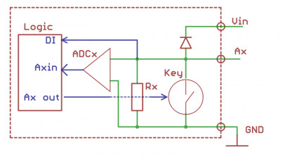
[[File:Ax.png|thumb|400px| Equivalent channels A1-A3 scheme]] | |||
[[File:А5.png|thumb|400px|Equivalent channels A4-A5 scheme]] | |||
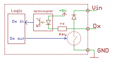
[[File:Dx.png|thumb|400px|Equivalent channels Dx scheme]] | |||
Versatile channels consist of input and output stages that operate simultaneously, as well as protective diodes (connected to one terminal of the channel). | |||
Output stage consists of the Tx switching element. | |||
Tx key grounds the outputs. | |||
Under control of the controller logical boards, the Tx key may be one of 2 states: | |||
*Active (closed); 0 is at the channel output. | |||
*Inactive (open), high impedance. Such outputs are called “open collectors”. | |||
Input stage of Ax channel consists of an analogue-to-digital converter ADCx and an input resistor Rx. Input resistance of the ADCx is high. It is always ON and does not affect the channel operation as it works in output mode. In input mode the Tx key is inactive (open) and, thus, does not affect voltage measuring at the channel terminals. Input resistance of the channel in input mode is formed by the Rx resistor. If no other circuits are connected to the channel terminals, the resistor downs the input voltage to zero, and the ADCx converter will read 0. | |||
In input mode the Tx | |||
If the channel | |||
А4 and А5 support binary input function DI: more than 3V at the terminal is considered as triggering of the input. | А4 and А5 support binary input function DI: more than 3V at the terminal is considered as triggering of the input. | ||
| Строка 250: | Строка 243: | ||
== Power Supply == | === Power Supply === | ||
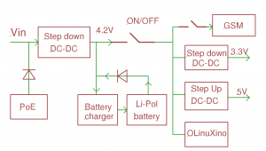
[[File:Питание версии4.png|thumb|300px|Блок-схема питания WB 4]] | [[File:Питание версии4.png|thumb|300px|Блок-схема питания WB 4]] | ||
| Строка 259: | Строка 252: | ||
=== External power source === | === External power source === | ||
Допустимый диапазон питания 7-24В. | |||
Среднее потребление платы - 1,5-2 Вт. Но т.к. модуль GSM потребляет импульсно до 8 Вт, рекомендуется использовать блоки питания с мощностью не менее 10 Вт. | |||
Разъем питания под стандартный jack 5.5x2.1мм, также входное напряжение можно подключать к клеммам Vin и GND. | |||
| Строка 269: | Строка 262: | ||
=== Power over Ethernet === | === Power over Ethernet === | ||
Поддерживается питание по кабелю Ethernet. Подробнее смотрите [[Special:MyLanguage/Power over Ethernet|Power over Ethernet]]. | |||
=== | === Аккумулятор === | ||
Wiren Board позволяет подключить Li-Ion (Li-Pol) аккумулятор c максимальным напряжением 4.2В. При подключении питания аккумулятор заряжается током до 0,5 А. | |||
Есть защита от зарядки при отрицательных температурах. Но защита от переразряда аккумулятора отсутствует, поэтому настоятельно рекомендуется использовать аккумуляторы с встроенной схемой защиты. | |||
''' | '''Соблюдайте полярность подключения аккумулятора!''' | ||
== | == Работа с клеммами WAGO 250 == | ||
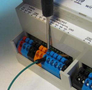
[[File:Wago.jpeg|thumb|300px| | [[File:Wago.jpeg|thumb|300px|Работа с клеммами WAGO 250]] | ||
В качестве интерфейсных клемм в контроллере | |||
применены клеммы WAGO 250 Series. | |||
Это самозажимные клипсы. При вставке очищенного | |||
одножильного провода в гнездо, он автоматически | |||
зажимается пружинной защѐлкой. | |||
Для вставки многожильных проводов, необходимо отжать | |||
пружину, нажав на кнопку клипсы. Кнопка имеет паз под | |||
шлицевую отвертку. | |||
Для извлечения провода, нужно отжать пружину, нажав на | |||
кнопку клипсы, и вытащить провод. | |||
== Wi-Fi, GSM, 433MHz | == Антенны Wi-Fi, GSM, 433MHz == | ||
Wi-Fi | Антенна Wi-Fi расположена внутри корпуса. | ||
GSM | Антенны GSM и радио 433MHz подключаются к SMA разъемам на корпусе. | ||
При слабом сигнале GSM рекомендуется использовать выносную антенну и располагать ее вдали от контроллера. | |||
== | == Схемы подключения периферии == | ||
[[File:Relay.png|thumb|300px| | [[File:Relay.png|thumb|300px|Пример подключения реле]] | ||
[[File:Button.png|thumb|400px| | [[File:Button.png|thumb|400px|Пример подключения кнопки]] | ||
=== | === Управление низковольтной нагрузкой === | ||
12/ | Реле на 12/24В, светодиоды, вентиляторы, сигнальные лампы и т. д. | ||
Напряжение питания контроллера должно быть не меньше напряжения подключаемой нагрузки. | |||
Подключите "+" нагрузки к "+" источника питания, а "-" к клеммам Ax или Dx. | |||
Если используется несколько каналов, и суммарный ток больше 5 А, подключите несколько клемм GND к "-" источника питания. | |||
При управлении индуктивной нагрузкой (реле), возникают всплески напряжения. | |||
Для защиты от перенапряжения в контроллер встроены защитные диоды. Никаких внешних защитных элементов не требуется. | |||
=== | === Контакторы с управляющим напряжением 220В === | ||
Подключите управляющую катушку контактора через реле WB (см. рисунок) | |||
Реле WB содержит демпфирующую RC-цепочку и TVS. Никакие внешние компоненты не требуются. | |||
=== | === Датчики с аналоговым выходом по напряжению === | ||
Подключите землю устройства к клемме GND, или соедините с общей земляной шиной. | |||
Выход датчика подключается к одному из клемм Ах или Rx. | |||
Каналы Ах/Rx имеют разные диапазоны измеряемых напряжений. Подберите оптимальный канал для вашего датчика. | |||
=== | === Датчики с аналоговым токовым выходом === | ||
WB | Специальных токовых входов в WB нет, но можно, используя резистор 100-300Ом, ток преобразовать в напряжение и подключить как в предыдущем пункте. | ||
=== | === Датчики с резистивным выходом === | ||
Входы R1 R2 предназначены для измерения сопротивлений в диапазоне 1-100кОм. | |||
Измеряемое сопротивление подключается между GND и Rx. | |||
=== | === Датчики/счетчики с импульсными выходами/кнопки === | ||
Такие устройства формируют сигнал, замыкая подходящие к ним два провода. | |||
Подключите один провод к клемме GND, или соедините с общей земляной шиной. | |||
Второй провод подключите к клемме Dx. | |||
Некоторые счетчики имеют импульсный выход на оптроне, тогда два провода имеют полярность - "плюс" и "минус". | |||
В таком случае минус подключается к GND, "плюс" к Dx. | |||
=== | === Устройства с выходом открытый коллектор === | ||
Устройство и контроллер должны иметь общую землю. | |||
Выход "открытый коллектор" подключите к клемме Dx. | |||
| Строка 384: | Строка 388: | ||
=== RS-485 | === Подключение к сети RS-485 === | ||
See [[Special:MyLanguage/RS-485|RS-485]]. | See [[Special:MyLanguage/RS-485|RS-485]]. | ||
| Строка 397: | Строка 401: | ||
=== Example of device connection === | === Example of device connection === | ||
Test bench diagram - [[Special:MyLanguage/Файл:Стенд-hi.jpg|thumb|500px|Test bench diagram]] | |||
== | == Diagram and Drawing == | ||
Wiren Board 4 principle diagram - [[Файл:WB 4.3.pdf|Файл:WB 4.3.pdf]], scheme - [[Файл:WB 4.2 чертеж.pdf|Файл:WB 4.2 чертеж.pdf]] | Wiren Board 4 principle diagram - [[Файл:WB 4.3.pdf|Файл:WB 4.3.pdf]], scheme - [[Файл:WB 4.2 чертеж.pdf|Файл:WB 4.2 чертеж.pdf]] | ||
Версия 15:48, 17 июля 2015
Technical specifications
| Software | |
|---|---|
| Operating System | Debian Linux 7.0. Mainline kernel 3.19. |
| Controller | |
| CPU | Freescale i.MX233 454 MHz |
| RAM | DDR SDRAM 64 MB |
| ROM | MicroSD card 32 GB max |
| Wireless Interfaces | |
| Wi-Fi | 802.11 b/g/n 2.4 ГГц |
| GSM/GPRS | 900/1800 МГц. GPRS multi-slot class 10/8 max. 85.6 kbps (downlink). microSIM card, packaged |
| Radio module 433 MHz | RFM69H module. To communicate with Noolite devices, Oregon NRF24L01 sensors |
| Radio module 2.4 GHz | NRF24L01To communicate with similar NRF24 modules (optional) |
| Wired interfaces | |
| Ethernet | 10/100 Mbit/s, RJ-45 connector |
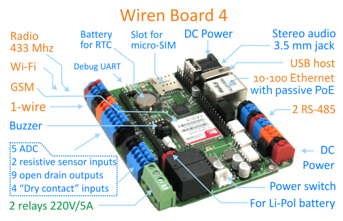
| USB 2.0 Host | 2 connectors (one connector is located inside the housing) |
| Audiooutput | 3.5 mm connector, stereo |
| 2xRS-485 (one of the ports is insulated) | Software support of Modbus RTU, ADICON/A-BUS/Uniel, and Smartbus G4 protocols |
| Debug console | Debug UART To be connected via USB-UART adapter |
| 2x 1-Wire | Connection of temperature and moister sensors |
| Connection of sensors | |
| 5x АЦП | 2x up to 24V , 3x - up to 5V |
| 2xInputs for resistive sensors | Connection of 10 kOhm thermistors. The controller can be used as ADC up to 3.3V |
| 4x"Dry contact" | Connection of pushbuttons, gerkons, counters with pulse outputs |
| 2x DI (digital input) | |
| Outputs | |
| 9x"Open collector" | 24V/2A, control of contactors, LED strip lights, etc. |
| 2xРеле | Up to 250V/3A, normally closed contacts |
| Other | |
| 8xGPIO | are multiplexed with other inputs/outputs |
| 1xSpeaker | "buzzer" |
| Real-time clock RTC | RTC Redundant battery |
| Watchdog timer | Separate hardware watchdog to perform full reset of the device |
| 1x Connector for extension module | Supported extension modules: * RS-232 extension module |
| Power supply | |
| Operating voltage | 9-24 V |
| Power consumption | <3 W (maximum 12 W) |
| Redundant battery | Operation Li-ion batteries are supported |
| Passive Power over Ethernet | Passsive Power over Ethernet |
| Overall dimensions | board - 103x87x20 mm, housing for DIN rail installation 6U |
| Operation | Operating temperature - 0..70C (-40..85C by request) Varnish coating for moister protection |
Terminal blocks
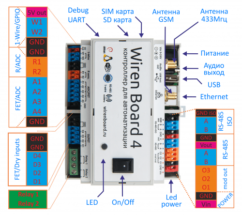
Some terminal blocks can be used to perform several functions. Ref. description of inputs and outputs and Port multiplexing article.
|
legend |
Max. V, I | state default | Functions | ||||
| Upper row, right block | |||||||
|---|---|---|---|---|---|---|---|
| Vin | 24V | Input voltage | |||||
| GND | |||||||
| O1 | Inputs/outputs of extension module | ||||||
| O2 | |||||||
| O3 | |||||||
| A | 30 V | 0V | Uninsulated port RS-485 | ||||
| B | 30 V | +5V | |||||
| (9-24)V_OUT | 24V | Input voltage (output) to power devices via RS-485 bus | |||||
| GND | |||||||
| A-iso | 30 V | 0V | Optic isolated RS-485 RS-485 | ||||
| B-iso | 30 V | +5V | |||||
| GND-iso | Grounding of optic isolated RS-485 | ||||||
| Lower row, left block | |||||||
| 5V out | 5V, 0.5A | 5V | output 5V (for 1-Wire sensors) | ||||
| W1 | 30V | 3.3V | 1-Wire, GPIO | ||||
| W2 | |||||||
| R1 | 5V | High Z | Resistive sensors,ADC, digital inputs (GPIO) without retightening | ||||
| R2 | |||||||
| A1 | Vin , 2A | High Z | "Open collector" outputs, ADC | ||||
| A2 | |||||||
| A3 | |||||||
| A4 | Vin , 2A | High Z | "Open collector" outputs, ADC , digital inputs DI | ||||
| A5 | |||||||
| GND | |||||||
| Lower row, right block | |||||||
| GND | |||||||
| GND | |||||||
| D1 | Vin , 2A | +5V | "Open collector" outputs, "dry contact" inputs | ||||
| D2 | |||||||
| D3 | |||||||
| D4 | |||||||
| Relay1 | 250, 2A | is open | first relay | ||||
| Relay2 | second relay | ||||||
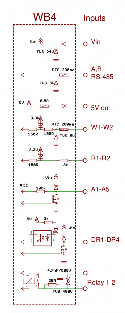
Input protection
As compared to version 3, input protection and general noise protection are significantly improved.
- Protection of all inputs from power supply voltage (up to 24 V) and pulse noise.
- Protection from reverse polarity.
- One optic isolated RS-485 port.
- Diode protection of keys at Ax and Dx inputs from inductive loads.
- Protection from relay contact sparking.
Versatile inputs/outputs Ax and Dx
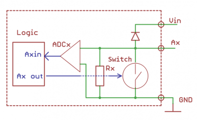
Versatile channels consist of input and output stages that operate simultaneously, as well as protective diodes (connected to one terminal of the channel).
Output stage consists of the Tx switching element. Tx key grounds the outputs. Under control of the controller logical boards, the Tx key may be one of 2 states:
- Active (closed); 0 is at the channel output.
- Inactive (open), high impedance. Such outputs are called “open collectors”.
Input stage of Ax channel consists of an analogue-to-digital converter ADCx and an input resistor Rx. Input resistance of the ADCx is high. It is always ON and does not affect the channel operation as it works in output mode. In input mode the Tx key is inactive (open) and, thus, does not affect voltage measuring at the channel terminals. Input resistance of the channel in input mode is formed by the Rx resistor. If no other circuits are connected to the channel terminals, the resistor downs the input voltage to zero, and the ADCx converter will read 0.
А4 and А5 support binary input function DI: more than 3V at the terminal is considered as triggering of the input.
Input stage of Dx channels consists of a circuit for connection of dry contacts. This stage continuously provides 5V voltage at the terminal. In input mode the Tx key is inactive (open). When the terminal is grounded, small current (2 mA) flows via the channel. Controller considers that as triggering of the input. Closing of the Tx key is considered as triggering of the input. In output mode the output stage does not affect the channel operation, provided that a more than 5 V load is connected to the channel.
Resistive Inputs
Each terminal is connected to internal adjustable current source. The controller measures current flowing through the sensor and simultaneously measures the terminal voltage to calculate the resistance value. If necessary and if the corresponding program is available, resistive inputs may be used as additional analogue/binary ones.
Extension modules
Ref. the corresponding articles to describe connection and software operation:
- Wiren Board 4: RS-232 extension module
- Wiren Board 4: CAN extension module
- Wiren Board 4: UART-CAN extension module
Power Supply
External power source
Допустимый диапазон питания 7-24В. Среднее потребление платы - 1,5-2 Вт. Но т.к. модуль GSM потребляет импульсно до 8 Вт, рекомендуется использовать блоки питания с мощностью не менее 10 Вт.
Разъем питания под стандартный jack 5.5x2.1мм, также входное напряжение можно подключать к клеммам Vin и GND.
Power over Ethernet
Поддерживается питание по кабелю Ethernet. Подробнее смотрите Power over Ethernet.
Аккумулятор
Wiren Board позволяет подключить Li-Ion (Li-Pol) аккумулятор c максимальным напряжением 4.2В. При подключении питания аккумулятор заряжается током до 0,5 А.
Есть защита от зарядки при отрицательных температурах. Но защита от переразряда аккумулятора отсутствует, поэтому настоятельно рекомендуется использовать аккумуляторы с встроенной схемой защиты.
Соблюдайте полярность подключения аккумулятора!
Работа с клеммами WAGO 250
В качестве интерфейсных клемм в контроллере применены клеммы WAGO 250 Series. Это самозажимные клипсы. При вставке очищенного одножильного провода в гнездо, он автоматически зажимается пружинной защѐлкой. Для вставки многожильных проводов, необходимо отжать пружину, нажав на кнопку клипсы. Кнопка имеет паз под шлицевую отвертку. Для извлечения провода, нужно отжать пружину, нажав на кнопку клипсы, и вытащить провод.
Антенны Wi-Fi, GSM, 433MHz
Антенна Wi-Fi расположена внутри корпуса.
Антенны GSM и радио 433MHz подключаются к SMA разъемам на корпусе.
При слабом сигнале GSM рекомендуется использовать выносную антенну и располагать ее вдали от контроллера.
Схемы подключения периферии
Управление низковольтной нагрузкой
Реле на 12/24В, светодиоды, вентиляторы, сигнальные лампы и т. д.
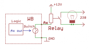
Напряжение питания контроллера должно быть не меньше напряжения подключаемой нагрузки. Подключите "+" нагрузки к "+" источника питания, а "-" к клеммам Ax или Dx. Если используется несколько каналов, и суммарный ток больше 5 А, подключите несколько клемм GND к "-" источника питания. При управлении индуктивной нагрузкой (реле), возникают всплески напряжения. Для защиты от перенапряжения в контроллер встроены защитные диоды. Никаких внешних защитных элементов не требуется.
Контакторы с управляющим напряжением 220В
Подключите управляющую катушку контактора через реле WB (см. рисунок) Реле WB содержит демпфирующую RC-цепочку и TVS. Никакие внешние компоненты не требуются.
Датчики с аналоговым выходом по напряжению
Подключите землю устройства к клемме GND, или соедините с общей земляной шиной. Выход датчика подключается к одному из клемм Ах или Rx. Каналы Ах/Rx имеют разные диапазоны измеряемых напряжений. Подберите оптимальный канал для вашего датчика.
Датчики с аналоговым токовым выходом
Специальных токовых входов в WB нет, но можно, используя резистор 100-300Ом, ток преобразовать в напряжение и подключить как в предыдущем пункте.
Датчики с резистивным выходом
Входы R1 R2 предназначены для измерения сопротивлений в диапазоне 1-100кОм. Измеряемое сопротивление подключается между GND и Rx.
Датчики/счетчики с импульсными выходами/кнопки
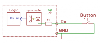
Такие устройства формируют сигнал, замыкая подходящие к ним два провода. Подключите один провод к клемме GND, или соедините с общей земляной шиной. Второй провод подключите к клемме Dx. Некоторые счетчики имеют импульсный выход на оптроне, тогда два провода имеют полярность - "плюс" и "минус". В таком случае минус подключается к GND, "плюс" к Dx.
Устройства с выходом открытый коллектор
Устройство и контроллер должны иметь общую землю. Выход "открытый коллектор" подключите к клемме Dx.
Network connection of 1-Wire
Connect the device ground to the GND terminal or a common grounding bus. Connect the data line to one of 1-Wire terminals. Connect the power line to 5V terminal (internal power source). It is allowed to use external power sources of 1-Wire bus.
If a passive power source is used, the power terminals of all sensors must be connected to the grounding bus. In such cases the bus will consist of two wires connected to 1-Wire and GND, respectively.
Подключение к сети RS-485
See RS-485.
Wiren Board 4 controllers are equipped with two RS-485 ports. One of them is galvanic insulated, the other one is not. If the RS-485 network is quite large, it is better use the insulated port for connection. Lines A and B are connected to A and B terminals, respectively. The signal ground (if any) must be connected to the GNDiso terminal.
A and B lines are often accompanied by another pair of wires used to power devices connected to the bus. In such cases it is necessary to use GND and Vout terminals. Current in power wires must not exceed 1 A.
Example of device connection
Test bench diagram - thumb|500px|Test bench diagram
Diagram and Drawing
Wiren Board 4 principle diagram - Файл:WB 4.3.pdf, scheme - Файл:WB 4.2 чертеж.pdf
