Wiren Board 5:Аппаратная часть/en: различия между версиями
Fizikdaos (обсуждение | вклад) (Новая страница: «=== Battery ===») |
|||
| (не показаны 103 промежуточные версии 3 участников) | |||
| Строка 1: | Строка 1: | ||
<languages/> | <languages/> | ||
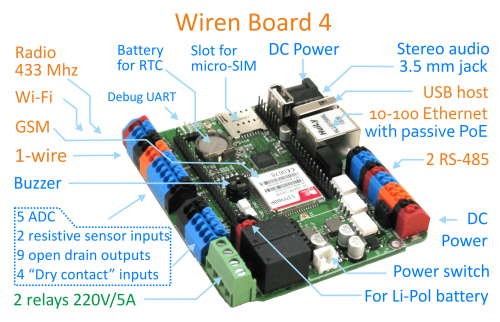
[[File:WB4-2.png| thumb | 500px|Wiren Board 4]] | |||
==Technical specifications== | |||
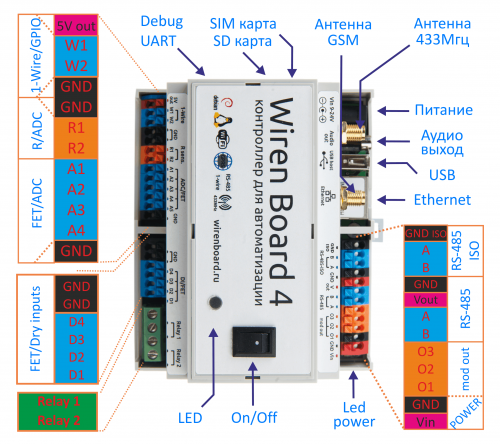
{| border="1" width=" | [[File:WB4.png| thumb | 500px|Wiren Board 4]] | ||
!colspan="2" | ''' | |||
{| border="1" width="45%" class="wikitable" style="text-align:center" | |||
!colspan="2" | '''Software''' | |||
|- | |- | ||
| | | Operating System || Debian Linux 7.0. Mainline kernel 3.19. | ||
|- | |- | ||
| | !colspan="2" | '''Controller''' | ||
|- | |- | ||
| | | CPU || [[Special:MyLanguage/Freescale i.MX287|Freescale i.MX287]] 454 MHz | ||
|- | |- | ||
|| | || RAM || DDR2 SDRAM 128 MB | ||
|- | |- | ||
|| | || ROM || 4 GB eMMC | ||
|- | |-} | ||
!colspan="2" | '''Wireless Interfaces''' | !colspan="2" | '''Wireless Interfaces''' | ||
|- | |- | ||
| [[Special:MyLanguage/Wi-Fi|Wi-Fi]] || 802.11 b/g/n 2.4 GHz | | [[Special:MyLanguage/Wi-Fi|Wi-Fi]] || 802.11 b/g/n 2.4 GHz | ||
|- | |- | ||
|| [[Special:MyLanguage/GSM/GPRS|GSM/GPRS]] || | || [[Special:MyLanguage/GSM/GPRS|GSM/GPRS]] || 900/1800 MHz. GPRS multi-slot class 10/8 max. 85.6 kbps (downlink). microSIM card, packaged | ||
microSIM card | |||
|- | |- | ||
|| Bluetooth ||4.0, Bluetooth Low Energy | || Bluetooth ||4.0, Bluetooth Low Energy | ||
|- | |- | ||
|| | || Radio module 433 MHz || RFM69H module. To communicate with [[Special:MyLanguage/Supported devices |Noolite]] devices, [[Special:MyLanguage/Supported devices |Oregon]] sensors | ||
To communicate with [[Special:MyLanguage/ | |||
|- | |- | ||
|| [[ | || [[Z-Wave]] || ''(option)'' | ||
|- | |- | ||
|| [[ | || [[IR-port]] || ''(external transceiver)'' | ||
|- | |- | ||
!colspan="2"| '''Wired Interfaces''' | !colspan="2"| '''Wired Interfaces''' | ||
|- | |- | ||
| Ethernet || 10/100 Mbit/s, 8P8C connector, passive PoE | | Ethernet || 10/100 Mbit/s, 8P8C connector, passive PoE | ||
|- | |- | ||
|| USB 2.0 || | || USB 2.0 || 1 connecor. Mode operation USB Host or USB Device | ||
|- | |- | ||
|| [[Special:MyLanguage/Аудиовыход| | || [[Special:MyLanguage/Аудиовыход|Audiooutput]] || Digital audio - S/PDIF, TOSLINK or RCA connector | ||
TOSLINK or RCA connector | |||
|- | |- | ||
||2x[[Special:MyLanguage/RS-485|RS-485]] || | ||2x[[Special:MyLanguage/RS-485|RS-485]] ||uninsulated. | ||
Software support | Software support of Modbus RTU, ADICON/A-BUS/Uniel, HDL, Mercury, Milur | ||
|- | |- | ||
||[[Special:MyLanguage/CAN|CAN]] || multiplexed with one | ||[[Special:MyLanguage/CAN|CAN]] || are multiplexed with one RS-485. | ||
|- | |- | ||
|| | || Debug console || [[Special:MyLanguage/Debug UART|Debug UART]] To be connected via USB-UART adapter. | ||
|- | |- | ||
|| [[Special:MyLanguage/1-Wire|1-Wire]] || | || [[Special:MyLanguage/1-Wire|1-Wire]] || Connection of temperature sensor | ||
|- | |- | ||
!colspan="2"| '''Connection of sensors''' | |||
!colspan="2"| ''' | |||
|- | |- | ||
| 4x[[Special:MyLanguage/ADC | ADC]] || 0- | | 4x[[Special:MyLanguage/ADC | ADC]] || range 0-24V | ||
|- | |- | ||
||2x[[Special:MyLanguage/Входы для резистивных датчиков| | ||2x[[Special:MyLanguage/Входы для резистивных датчиков|Inputs for resistive sensors]] | ||
|| | || Connection of 10 kOhm thermistors, The controller can be used as ADC up to 3.3V. | ||
|- | |- | ||
|| 4x[[Special:MyLanguage/DI | DI (digital | || 4x[[Special:MyLanguage/DI | DI (digital input)]] | ||
|- | |- | ||
!colspan="2"| '''Outputs''' | !colspan="2"| '''Outputs''' | ||
|- | |- | ||
| 4x[[Special:MyLanguage/Управление низковольтной нагрузкой|"Open collector"]] || 28V/2A, | | 4x[[Special:MyLanguage/Управление низковольтной нагрузкой|"Open collector"]] || 28V/2A, control of contactors, LED strip lights, etc. | ||
|- | |- | ||
!colspan="2"| '''Other''' | |||
!colspan="2"| '''Other | |||
|- | |- | ||
| 2x[[Special:MyLanguage/GPIO|GPIO]] || are multiplexed with other inputs/outputs | | 2x[[Special:MyLanguage/GPIO|GPIO]] || are multiplexed with other inputs/outputs | ||
|- | |- | ||
||1x[[Special:MyLanguage/Buzzer| | ||1x[[Special:MyLanguage/Buzzer|Speaker]]|| "buzzer". | ||
|- | |- | ||
|| Real-time clock || [[Special:MyLanguage/RTC|RTC]] | || Real-time clock || [[Special:MyLanguage/RTC|RTC]] clock battery | ||
|- | |- | ||
|| Watchdog timer || Separate hardware watchdog to perform full reset of the device | || Watchdog timer || Separate hardware watchdog to perform full reset of the device | ||
|- | |- | ||
|| | || 2xConnector for extension modules || | ||
|- | |- | ||
|| | || 1xConnector for input/output modules || series connection of modules, up to 8. | ||
|- | |- | ||
{ | { | ||
!colspan="2"| '''Power supply''' | !colspan="2"| '''Power supply''' | ||
|- | |- | ||
|Supply voltage | |Supply voltage | ||
| | |8-26 V | ||
|-| Operating voltage || 9-28 V | |||
|| Power consumption || <3 W (maximum 12 W) | |||
|- | |||
| Redundant battery || [[WBMZ-BATTERY - модуль резервного питания|backup power supply module]] (option) | |||
|- | |- | ||
|| Power | ||Passive Power over Ethernet || [[Special:MyLanguage/Power over Ethernet | Passsive Power over Ethernet]] | ||
|- | |- | ||
| | || Overall dimensions|| housing for DIN rail installation 6U, 106.25x90.2x57.5 mm. | ||
size without housing: 103x87x20 mm. | |||
|- | |- | ||
|| | ||Operation|| Operating temperature- -25...+85 С | ||
(-40..+85 С by request). | |||
Conformal coating of pcb for moister protection. | |||
|- | |- | ||
|} | |} | ||
== Terminal blocks == | == Terminal blocks == | ||
[[Файл:WB5inputs.png|thumb|400px|Схема защиты входов и выходов]] | |||
Some terminal blocks can be used to perform more than one function. See the detailed description of input/output and [[Special:MyLanguage/Мультиплексирование портов|the Port multiplexing]] article. | Some terminal blocks can be used to perform more than one function. See the detailed description of input/output and [[Special:MyLanguage/Мультиплексирование портов|the Port multiplexing]] article. | ||
{| border="1" width="45%" class="wikitable" style="text-align:center" | |||
{| border="1" width=" | | | ||
| | |||
'''legend''' | '''legend''' | ||
|| '''Max. V, I''' | || '''Max. V, I''' | ||
| Строка 131: | Строка 124: | ||
| '''Vin''' || 28V || ||Input voltage | | '''Vin''' || 28V || ||Input voltage | ||
|- | |- | ||
| '''GND''' || || ||power supply | | '''GND''' || || ||"ground", minus power supply | ||
|- | |- | ||
! colspan="6"| Upper row, right block | ! colspan="6"| Upper row, right block | ||
| Строка 147: | Строка 140: | ||
| '''O3''' | | '''O3''' | ||
|- | |- | ||
! colspan="8"| Lower row, right block | ! colspan="8"| Lower row, right block} | ||
|- | |- | ||
| '''A1''' || rowspan="4"| 24V , 2A || rowspan="4"| High Z || rowspan="4" |[[Special:MyLanguage/Управление низковольтной нагрузкой|" | | '''A1''' || rowspan="4"| 24V , 2A || rowspan="4"| High Z || rowspan="4" |[[Special:MyLanguage/Управление низковольтной нагрузкой|Outputs "open collector"]], [[Special:MyLanguage/ADC|ADC]] | ||
|- | |- | ||
| '''A2''' | | '''A2''' | ||
| Строка 157: | Строка 151: | ||
| '''A4''' | | '''A4''' | ||
|- | |- | ||
| '''R1''' || rowspan="2"| 5V || rowspan="2"|High Z || rowspan="2" |Resistive sensors, [[Special:MyLanguage/ADC|ADC]], digital inputs | | '''R1''' || rowspan="2"| 5V || rowspan="2"|High Z || rowspan="2" |Resistive sensors, [[Special:MyLanguage/ADC|ADC]], digital inputs (GPIO) without retightening | ||
|- | |- | ||
| '''R2''' | | '''R2''' | ||
| Строка 165: | Строка 159: | ||
| '''W1''' || 30V || 3.3V || [[Special:MyLanguage/1-Wire|1-Wire]], GPIO | | '''W1''' || 30V || 3.3V || [[Special:MyLanguage/1-Wire|1-Wire]], GPIO | ||
|- | |- | ||
| '''5V out''' || 5V, 0.5A || 5V || 5V | | '''5V out''' || 5V, 0.5A || 5V || Output 5V. Shutdown current is exceeded. Software control. | ||
|- | |- | ||
| '''A''' || 30 V || 0V || rowspan="2"|connector [[Special:MyLanguage/RS-485|RS-485]] (/dev/ttyAPP1) | | '''A''' || 30 V || 0V || rowspan="2"|connector [[Special:MyLanguage/RS-485|RS-485]] (/dev/ttyAPP1) | ||
|- | |- | ||
| '''B''' || 30 V || +5V | | '''B''' || 30 V || +5V | ||
|- | |- | ||
|- | |- | ||
| '''L''' || 30 V || 0V || rowspan="2"|connector CAN or [[Special:MyLanguage/RS-485|RS-485]] (/dev/ttyAPP4). | | '''L''' || 30 V || 0V || rowspan="2"|connector CAN or [[Special:MyLanguage/RS-485|RS-485]] (/dev/ttyAPP4). | ||
| Строка 177: | Строка 175: | ||
| '''H''' || 30 V || +5V | | '''H''' || 30 V || +5V | ||
|- | |- | ||
|} | |} | ||
== Input protection == | == Input protection == | ||
#All inputs are protected from applying the power supply voltage (up to 24 V) and transient noise. | #All inputs are protected from applying the power supply voltage (up to 24 V) and transient noise. | ||
#Wiren Board 5 is protected against reverse polarity | #Wiren Board 5 is protected against reverse polarity | ||
| Строка 185: | Строка 185: | ||
== Multifunctional inputs/outputs A1-A4== | == Multifunctional inputs/outputs A1-A4== | ||
[[Файл:Ax2.png|thumb|400px|Equivalent circuit of A1-A4 channels]] | [[Файл:Ax2.png|thumb|400px|Equivalent circuit of A1-A4 channels]] | ||
| Строка 190: | Строка 191: | ||
Output stage consists of the Tx switch. The Tx switch can connect the corresponding output with ground. | Output stage consists of the Tx switch. The Tx switch can connect the corresponding output with ground. | ||
The state of the switch is controlled by logic circuits inside the controller. The switch may be one of 2 states: | The state of the switch is controlled by logic circuits inside the controller. The switch may be one of 2 states: | ||
*Active (closed); channel output is connected to ground (0V) | *Active (closed); channel output is connected to ground (0V) | ||
*Inactive (open), high impedance. | *Inactive (open), high impedance. | ||
Such outputs are called “open collectors” | |||
Input stage of Ax channel consists of an analogue-to-digital converter ADCx and an input resistor Rx. | |||
The ADC has a high impedance, so it doesn't affect the channel operation even if the channel works as output. | |||
In input mode the Tx switch is inactive (open) and, thus, does not affect voltage measuring at the channel terminals. Input resistance of the channel in input mode is determined by the Rx resistance. | |||
If the channel terminal is left floating, the input voltage measured by ADCs is pulled down to zero by the Rx resistance. | |||
Аx channels support binary input function DI: more than 3V at the terminal is considered as triggering of the input. | |||
== Resistive Inputs R1 and R2 == | |||
The | In the default mode each terminal is connected to internal adjustable current source. | ||
The controller provides a predetermined current through the sensor, thus measuring the voltage drop on it. | |||
Of the known current and voltage values, software of the controller calculates the resistance of the sensor. | |||
In | Each input also [[ADC#Измерение сопротивлений|can be switched]] to a conventional analog input settings. | ||
In this mode, the power supply is turned off and measure the input voltage in the range 0-3.0V. | |||
If the | The inputs R1-R2 also act as binary inputs. | ||
While the current source is activated (the default mode) the input is tucked up to the power supply. | |||
If no entry to connected, this state is perceived as a logical unit. | |||
If you connect the terminals to the ground, this corresponds to a logical zero. | |||
External buttons, sensors, etc. in this mode must be connected between the Rx and GND. | |||
In an alternate mode while the current source is unactivated, the input is tucked up to ground. | |||
A logical zero corresponds to the input, to which nothing is connected; logical unit - the entrance to which a voltage is applied > 3B. | |||
In this mode external buttons, sensors, etc. must be connected between the Rx and terminal board 5V out, or plus of supply. | |||
== Extension modules == | |||
Look the relevant articles to describe the connection and operation of the software: | |||
* [[Wiren Board 5: Модуль расширения RS-232]] | |||
* [[Wiren Board 5: Модуль расширения CAN-ISO | Модуль расширения CAN (Изолированный)]] | |||
* [[Wiren Board 5: Модуль расширения RS485-ISO | Модуль расширения RS-485 (Изолированный)]] | |||
* [[Wiren Board 5: Модуль расширения ADC | Модуль расширения АЦП]] - входы напряжения, входы 0-20мА, датчики PT100 и PT1000 | |||
* [[Wiren Board 5: Модуль расширения DAC | Модуль расширения ЦАП]] - выходы 0-10В | |||
* [[Wiren Board 5: Модуль расширения DI | Модуль входов "сухой контакт"]] | |||
* [[Wiren Board 5: Модуль расширения GPS/Glonass]] | |||
== Power Supply == | |||
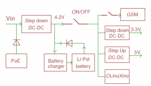
[[File:Питание версии4.png|thumb|300px|Блок-схема питания WB 4]] | |||
=== External power source === | |||
Allowed voltage range is 7-28 V. | |||
Average power consumption of the board is 1.5-2 W, but the GSM module may temporally consume up to 8 W. Therefore, it is recommended to use at least 10 W power sources. | |||
A standard connector jack 5.5x2.1 mm is provided for connection to the power source. Input power can also be connected to Vin and GND terminals. | |||
=== Power over Ethernet === | |||
It is possible to power the device via an Ethernet cable. Ref.[[Special:MyLanguage/Power over Ethernet|Power over Ethernet]]. | |||
=== Battery === | |||
Wiren Board позволяет подключить внутренний [[WBMZ-BATTERY - модуль резервного питания | модуль резервного питания WBMZ-BATTERY ]] с Li-Ion (Li-Pol) аккумулятором. | |||
== Работа с нажимными клеммами == | |||
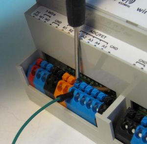
[[File:Wago.jpeg|thumb|300px|Работа с самозажимными клеммами]] | |||
В качестве интерфейсных клемм в контроллере | |||
применены клеммы "тип 250". | |||
Это самозажимные клипсы. При вставке очищенного | |||
одножильного провода в гнездо, он автоматически | |||
зажимается пружинной защѐлкой. | |||
Для вставки многожильных проводов, необходимо отжать | |||
пружину, нажав на кнопку клипсы. Кнопка имеет паз под | |||
шлицевую отвертку. | |||
Для извлечения провода, нужно отжать пружину, нажав на | |||
кнопку клипсы, и вытащить провод. | |||
== Антенны Wi-Fi, GSM, 433MHz == | |||
Антенны Wi-Fi, GSM и радио 315/433MHz подключаются к SMA разъемам. | |||
При слабом сигнале GSM рекомендуется использовать выносную антенну и располагать ее вдали от контроллера. | |||
== Схемы подключения периферии == | |||
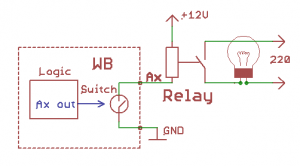
[[File:Relay.png|thumb|300px|Пример подключения реле]] | |||
=== Управление низковольтной нагрузкой === | |||
Реле на 12/24В, светодиоды, вентиляторы, сигнальные лампы и т. д. | |||
Подключите "+" нагрузки к "+" источника питания, а "-" к клеммам Ax. | |||
Если суммарный ток на каналах больше 2 А, дополнительно подключите клемму GND к "-" источника питания. | |||
При управлении индуктивной нагрузкой (реле), возникают всплески напряжения. | |||
Для защиты от перенапряжения в контроллер встроены защитные диоды - внешних защитных элементов не требуется. | |||
=== Датчики с аналоговым выходом по напряжению === | |||
Подключите землю устройства к клемме GND, или соедините с общей земляной шиной. | |||
Выход датчика подключается к одному из клемм Ах или Rx. | |||
Каналы Ах/Rx имеют разные диапазоны измеряемых напряжений. Подберите оптимальный канал для вашего датчика. | |||
=== Датчики с аналоговым токовым выходом === | |||
Специальных токовых входов в WB нет, но можно, используя резистор 100-300Ом, ток преобразовать в напряжение и подключить как в предыдущем пункте. | |||
Также для подключения токовых датчиков предназначен специальный [[Wiren Board 5: Модуль расширения ADC | модуль расширения]]. | |||
=== Датчики с резистивным выходом === | |||
Входы R1 и R2 предназначены для измерения сопротивлений в диапазоне 1-100кОм. | |||
Измеряемое сопротивление подключается между GND и Rx. | |||
Для более точного изменения сопротивлений, а также для подключения датчиков Pt100 и Pt1000 по двух- и трёх- проводным схемам | |||
предназначен специальный [[Wiren Board 5: Модуль расширения ADC | модуль расширения]]. | |||
=== Датчики/счетчики с импульсными выходами/кнопки === | |||
Такие устройства формируют сигнал, замыкая подходящие к ним два провода. | |||
Подключите один провод к источнику питания 5-24В. | |||
Второй провод подключите к клемме Аx. | |||
Некоторые счетчики имеют импульсный выход на оптроне, тогда два провода имеют полярность - "плюс" и "минус". | |||
В таком случае минус подключается к Аx, "плюс" к источнику питания. | |||
R1 | Для подключения также можно использовать входы R1 и R2 контроллера, как описано выше. | ||
Так же возможно подключение с использованием модуля расширения (см. следующий пункт). | |||
=== Устройства с выходом открытый коллектор === | |||
Устройство и контроллер должны иметь общую землю. | |||
Выход "открытый коллектор" подключите к клемме Dx модуля расширения. | |||
Для подключения также можно использовать входы R1 и R2 контроллера, как описано выше. | |||
=== Подключение к 1-Wire сети === | |||
Землю сети подключите к клемме GND или общей земляной шине. | |||
1-Wire | Линию данных к клемме 1-Wire. | ||
Линию питания к клемме 5Vout (внутренний источник питания). | |||
Допускается использовать внешние источники питания шины 1-Wire. | |||
При использовании пассивного питания, контакт питания каждого датчика соединяется с земляным проводом. | |||
В этом случае, шина прокладывается двумя проводами, подключаемыми соответственно к "1-Wire" и "GND". | |||
=== Подключение к сети RS-485 === | |||
Смотрите [[Special:MyLanguage/RS-485|RS-485]]. | |||
В Wiren Board 5 есть два порта RS-485. Второй порт мультиплексирован с портом CAN (L c A, H c B) | |||
Линии А В подключаются к клеммам А и В соответственно. Сигнальную землю (если есть) подключить к земле контроллера. | |||
Если сеть RS-485 достаточно протяженная, то для её подключения рекомендуется использовать [[Wiren Board 5: Модуль расширения RS485-ISO|модуль расширения с гальванически-изолированным RS-485]]. | |||
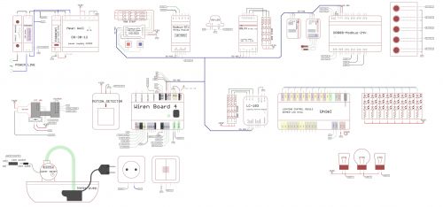
=== Пример подключения устройств === | |||
Схема испытательного стенда - [[Файл:Стенд-hi.jpg|thumb|500px|Схема стенда]] | |||
== | == Подключение устройств с использованием модулей расширения == | ||
=== Контакторы с управляющим напряжением 220В === | |||
Используйте модуль расширения с релейными выходами, например [[Модули ввода-вывода#Модуль релейных выходов (WBIO-DO-R3A-8)|WBIO-DO-R3A-8]]. | |||
Подключите управляющую катушку контактора через реле модуля расширения (см. рисунок). | |||
Модуль расширения содержит TVS, защищающий контакты реле от искрения. Внешние защитные компоненты не требуются. | |||
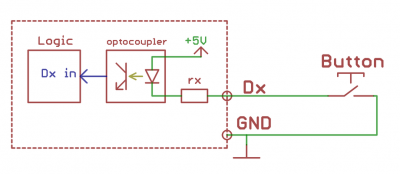
=== Датчики/счетчики с импульсными выходами/кнопки === | |||
[[File:Button.png|thumb|400px|Пример подключения кнопки]] | |||
[[File: | |||
Такие устройства формируют сигнал, замыкая подходящие к ним два провода. | |||
Для подключения к контроллеру один провод подключите к питанию (или клемме 5Vout), второй провод к клемме Ax. | |||
Так же можно использовать модуль расширения дискретных входов типа "сухой контакт" [[Модули ввода-вывода#Модуль дискретных входов типа "сухой контакт" (WBIO-DI-DR-8)|WBIO-DI-DR-8]]. | |||
Подключите один провод к клемме GND, или соедините с общей земляной шиной. | |||
Второй провод подключите к клемме Dx. | |||
Некоторые счетчики имеют импульсный выход на оптроне, тогда два провода имеют полярность - "плюс" и "минус". | |||
В таком случае минус подключается к GND, "плюс" к Dx. | |||
== | == Схема и чертеж == | ||
Принципиальная схема Wiren Board 4 - [[Файл:WB 4.3.pdf|Файл:WB 4.3.pdf]], чертёж - [[Файл:WB 4.2 чертеж.pdf|Файл:WB 4.2 чертеж.pdf]] | |||
== | == Список GPIO == | ||
Статья, описывающая подключение сигналов процессора к клеммникам, встроенной периферии и разъёмам расширения: | |||
[[Wiren Board 5:Список GPIO]] | |||
Версия 17:57, 24 ноября 2015
Technical specifications
| Software | |
|---|---|
| Operating System | Debian Linux 7.0. Mainline kernel 3.19. |
| Controller | |
| CPU | Freescale i.MX287 454 MHz |
| RAM | DDR2 SDRAM 128 MB |
| ROM | 4 GB eMMC |
| Wireless Interfaces | |
| Wi-Fi | 802.11 b/g/n 2.4 GHz |
| GSM/GPRS | 900/1800 MHz. GPRS multi-slot class 10/8 max. 85.6 kbps (downlink). microSIM card, packaged |
| Bluetooth | 4.0, Bluetooth Low Energy |
| Radio module 433 MHz | RFM69H module. To communicate with Noolite devices, Oregon sensors |
| Z-Wave | (option) |
| IR-port | (external transceiver) |
| Wired Interfaces | |
| Ethernet | 10/100 Mbit/s, 8P8C connector, passive PoE |
| USB 2.0 | 1 connecor. Mode operation USB Host or USB Device |
| Audiooutput | Digital audio - S/PDIF, TOSLINK or RCA connector |
| 2xRS-485 | uninsulated.
Software support of Modbus RTU, ADICON/A-BUS/Uniel, HDL, Mercury, Milur |
| CAN | are multiplexed with one RS-485. |
| Debug console | Debug UART To be connected via USB-UART adapter. |
| 1-Wire | Connection of temperature sensor |
| Connection of sensors | |
| 4x ADC | range 0-24V |
| 2xInputs for resistive sensors | Connection of 10 kOhm thermistors, The controller can be used as ADC up to 3.3V. |
| 4x DI (digital input) | |
| Outputs | |
| 4x"Open collector" | 28V/2A, control of contactors, LED strip lights, etc. |
| Other | |
| 2xGPIO | are multiplexed with other inputs/outputs |
| 1xSpeaker | "buzzer". |
| Real-time clock | RTC clock battery |
| Watchdog timer | Separate hardware watchdog to perform full reset of the device |
| 2xConnector for extension modules | |
| 1xConnector for input/output modules | series connection of modules, up to 8. |
| Power supply | |
| Supply voltage | 8-26 V |
| Power consumption | <3 W (maximum 12 W) |
| Redundant battery | backup power supply module (option) |
| Passive Power over Ethernet | Passsive Power over Ethernet |
| Overall dimensions | housing for DIN rail installation 6U, 106.25x90.2x57.5 mm.
size without housing: 103x87x20 mm. |
| Operation | Operating temperature- -25...+85 С
(-40..+85 С by request). Conformal coating of pcb for moister protection. |
Terminal blocks
Some terminal blocks can be used to perform more than one function. See the detailed description of input/output and the Port multiplexing article.
|
legend |
Max. V, I | state default | Functions | ||||
| Upper row, left block | |||||||
|---|---|---|---|---|---|---|---|
| Vin | 28V | Input voltage | |||||
| GND | "ground", minus power supply | ||||||
| Upper row, right block | |||||||
| O1 | Inputs/outputs of extension module | ||||||
| O2 | |||||||
| O3 | |||||||
| O1 | Inputs/outputs of extension module | ||||||
| O2 | |||||||
| O3 | |||||||
| Lower row, right block} | |||||||
| A1 | 24V , 2A | High Z | Outputs "open collector", ADC | ||||
| A2 | |||||||
| A3 | |||||||
| A4 | |||||||
| R1 | 5V | High Z | Resistive sensors, ADC, digital inputs (GPIO) without retightening | ||||
| R2 | |||||||
| GND | |||||||
| W1 | 30V | 3.3V | 1-Wire, GPIO | ||||
| 5V out | 5V, 0.5A | 5V | Output 5V. Shutdown current is exceeded. Software control. | ||||
| A | 30 V | 0V | connector RS-485 (/dev/ttyAPP1) | ||||
| B | 30 V | +5V | |||||
| L | 30 V | 0V | connector CAN or RS-485 (/dev/ttyAPP4).
Connection RS-485: A to terminal L, B to terminal H. | ||||
| H | 30 V | +5V | |||||
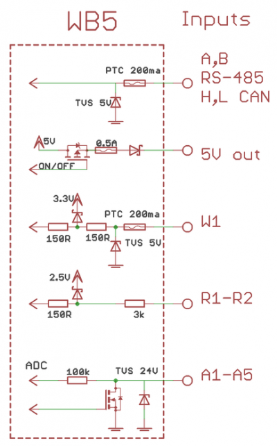
Input protection
- All inputs are protected from applying the power supply voltage (up to 24 V) and transient noise.
- Wiren Board 5 is protected against reverse polarity
- Low-side FET switches on Ax inputs are protected from negative voltage spikes from inductive loads.
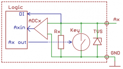
Multifunctional inputs/outputs A1-A4
Multifunctional channels consist of input and output stages are connected in parallel, as well as protective diodes (connected to one terminal of the channel).
Output stage consists of the Tx switch. The Tx switch can connect the corresponding output with ground.
The state of the switch is controlled by logic circuits inside the controller. The switch may be one of 2 states:
- Active (closed); channel output is connected to ground (0V)
- Inactive (open), high impedance.
Such outputs are called “open collectors”
Input stage of Ax channel consists of an analogue-to-digital converter ADCx and an input resistor Rx. The ADC has a high impedance, so it doesn't affect the channel operation even if the channel works as output. In input mode the Tx switch is inactive (open) and, thus, does not affect voltage measuring at the channel terminals. Input resistance of the channel in input mode is determined by the Rx resistance. If the channel terminal is left floating, the input voltage measured by ADCs is pulled down to zero by the Rx resistance.
Аx channels support binary input function DI: more than 3V at the terminal is considered as triggering of the input.
Resistive Inputs R1 and R2
In the default mode each terminal is connected to internal adjustable current source. The controller provides a predetermined current through the sensor, thus measuring the voltage drop on it. Of the known current and voltage values, software of the controller calculates the resistance of the sensor.
Each input also can be switched to a conventional analog input settings. In this mode, the power supply is turned off and measure the input voltage in the range 0-3.0V.
The inputs R1-R2 also act as binary inputs.
While the current source is activated (the default mode) the input is tucked up to the power supply. If no entry to connected, this state is perceived as a logical unit. If you connect the terminals to the ground, this corresponds to a logical zero. External buttons, sensors, etc. in this mode must be connected between the Rx and GND.
In an alternate mode while the current source is unactivated, the input is tucked up to ground. A logical zero corresponds to the input, to which nothing is connected; logical unit - the entrance to which a voltage is applied > 3B. In this mode external buttons, sensors, etc. must be connected between the Rx and terminal board 5V out, or plus of supply.
Extension modules
Look the relevant articles to describe the connection and operation of the software:
- Wiren Board 5: Модуль расширения RS-232
- Модуль расширения CAN (Изолированный)
- Модуль расширения RS-485 (Изолированный)
- Модуль расширения АЦП - входы напряжения, входы 0-20мА, датчики PT100 и PT1000
- Модуль расширения ЦАП - выходы 0-10В
- Модуль входов "сухой контакт"
- Wiren Board 5: Модуль расширения GPS/Glonass
Power Supply
External power source
Allowed voltage range is 7-28 V. Average power consumption of the board is 1.5-2 W, but the GSM module may temporally consume up to 8 W. Therefore, it is recommended to use at least 10 W power sources.
A standard connector jack 5.5x2.1 mm is provided for connection to the power source. Input power can also be connected to Vin and GND terminals.
Power over Ethernet
It is possible to power the device via an Ethernet cable. Ref.Power over Ethernet.
Battery
Wiren Board позволяет подключить внутренний модуль резервного питания WBMZ-BATTERY с Li-Ion (Li-Pol) аккумулятором.
Работа с нажимными клеммами
В качестве интерфейсных клемм в контроллере применены клеммы "тип 250". Это самозажимные клипсы. При вставке очищенного одножильного провода в гнездо, он автоматически зажимается пружинной защѐлкой. Для вставки многожильных проводов, необходимо отжать пружину, нажав на кнопку клипсы. Кнопка имеет паз под шлицевую отвертку. Для извлечения провода, нужно отжать пружину, нажав на кнопку клипсы, и вытащить провод.
Антенны Wi-Fi, GSM, 433MHz
Антенны Wi-Fi, GSM и радио 315/433MHz подключаются к SMA разъемам.
При слабом сигнале GSM рекомендуется использовать выносную антенну и располагать ее вдали от контроллера.
Схемы подключения периферии
Управление низковольтной нагрузкой
Реле на 12/24В, светодиоды, вентиляторы, сигнальные лампы и т. д.
Подключите "+" нагрузки к "+" источника питания, а "-" к клеммам Ax. Если суммарный ток на каналах больше 2 А, дополнительно подключите клемму GND к "-" источника питания.
При управлении индуктивной нагрузкой (реле), возникают всплески напряжения. Для защиты от перенапряжения в контроллер встроены защитные диоды - внешних защитных элементов не требуется.
Датчики с аналоговым выходом по напряжению
Подключите землю устройства к клемме GND, или соедините с общей земляной шиной. Выход датчика подключается к одному из клемм Ах или Rx. Каналы Ах/Rx имеют разные диапазоны измеряемых напряжений. Подберите оптимальный канал для вашего датчика.
Датчики с аналоговым токовым выходом
Специальных токовых входов в WB нет, но можно, используя резистор 100-300Ом, ток преобразовать в напряжение и подключить как в предыдущем пункте.
Также для подключения токовых датчиков предназначен специальный модуль расширения.
Датчики с резистивным выходом
Входы R1 и R2 предназначены для измерения сопротивлений в диапазоне 1-100кОм. Измеряемое сопротивление подключается между GND и Rx.
Для более точного изменения сопротивлений, а также для подключения датчиков Pt100 и Pt1000 по двух- и трёх- проводным схемам предназначен специальный модуль расширения.
Датчики/счетчики с импульсными выходами/кнопки
Такие устройства формируют сигнал, замыкая подходящие к ним два провода. Подключите один провод к источнику питания 5-24В. Второй провод подключите к клемме Аx. Некоторые счетчики имеют импульсный выход на оптроне, тогда два провода имеют полярность - "плюс" и "минус". В таком случае минус подключается к Аx, "плюс" к источнику питания.
Для подключения также можно использовать входы R1 и R2 контроллера, как описано выше.
Так же возможно подключение с использованием модуля расширения (см. следующий пункт).
Устройства с выходом открытый коллектор
Устройство и контроллер должны иметь общую землю. Выход "открытый коллектор" подключите к клемме Dx модуля расширения.
Для подключения также можно использовать входы R1 и R2 контроллера, как описано выше.
Подключение к 1-Wire сети
Землю сети подключите к клемме GND или общей земляной шине. Линию данных к клемме 1-Wire. Линию питания к клемме 5Vout (внутренний источник питания). Допускается использовать внешние источники питания шины 1-Wire.
При использовании пассивного питания, контакт питания каждого датчика соединяется с земляным проводом. В этом случае, шина прокладывается двумя проводами, подключаемыми соответственно к "1-Wire" и "GND".
Подключение к сети RS-485
Смотрите RS-485.
В Wiren Board 5 есть два порта RS-485. Второй порт мультиплексирован с портом CAN (L c A, H c B) Линии А В подключаются к клеммам А и В соответственно. Сигнальную землю (если есть) подключить к земле контроллера.
Если сеть RS-485 достаточно протяженная, то для её подключения рекомендуется использовать модуль расширения с гальванически-изолированным RS-485.
Пример подключения устройств
Схема испытательного стенда -
Подключение устройств с использованием модулей расширения
Контакторы с управляющим напряжением 220В
Используйте модуль расширения с релейными выходами, например WBIO-DO-R3A-8.
Подключите управляющую катушку контактора через реле модуля расширения (см. рисунок).
Модуль расширения содержит TVS, защищающий контакты реле от искрения. Внешние защитные компоненты не требуются.
Датчики/счетчики с импульсными выходами/кнопки
Такие устройства формируют сигнал, замыкая подходящие к ним два провода.
Для подключения к контроллеру один провод подключите к питанию (или клемме 5Vout), второй провод к клемме Ax.
Так же можно использовать модуль расширения дискретных входов типа "сухой контакт" WBIO-DI-DR-8.
Подключите один провод к клемме GND, или соедините с общей земляной шиной. Второй провод подключите к клемме Dx.
Некоторые счетчики имеют импульсный выход на оптроне, тогда два провода имеют полярность - "плюс" и "минус". В таком случае минус подключается к GND, "плюс" к Dx.
Схема и чертеж
Принципиальная схема Wiren Board 4 - Файл:WB 4.3.pdf, чертёж - Файл:WB 4.2 чертеж.pdf
Список GPIO
Статья, описывающая подключение сигналов процессора к клеммникам, встроенной периферии и разъёмам расширения: Wiren Board 5:Список GPIO
