Disassembling the controller case/en: различия между версиями
(Новая страница: «Installing: # Place the controller face up. # Insert the power switch of the controller into the hole on the cover. # Close all latches carefully.») |
FuzzyBot (обсуждение | вклад) (Обновление для соответствия новой версии исходной страницы.) |
||
| (не показаны 34 промежуточные версии 3 участников) | |||
| Строка 1: | Строка 1: | ||
<languages/> | <languages/> | ||
<div class="mw-translate-fuzzy"> | |||
{{DISPLAYTITLE: Disassembling the controller case }} | |||
===Tools=== | ===Tools=== | ||
To disassemble the controller, you will need a slotted screwdriver. | To disassemble the controller, you will need a slotted screwdriver. | ||
===Disassembling=== | ===Disassembling=== | ||
To disassemble the controller, you need to remove the back cover, which is held on by four latches, and extract the circuit board of controller from the case | To disassemble the controller, you need to remove the back cover, which is held on by four latches, and extract the circuit board of controller from the case. | ||
</div> | |||
# | # Положите контроллер задней крышкой кверху. | ||
# | # Вставьте отвертку между защелкой и основанием. Плавным вращательным движением отогните защелку и потяните заднюю крышку вверх. Проделайте тоже самое с остальными защелками. | ||
# | # С помощью отвертки отогните оставшиеся защелки и снимите крышку. | ||
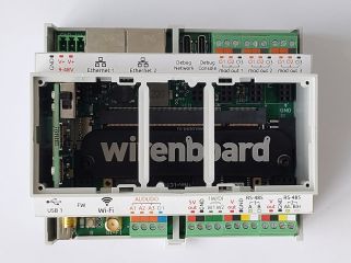
# | # Слегка отогните боковую стенку корпуса в месте, где расположен разъем для подключения внешних модулей, и вытолкните плату контроллера из корпуса. Не прилагайте больших усилий, чтобы не повредить разъем. | ||
<div class="mw-translate-fuzzy"> | |||
<gallery mode="packed" heights="150px"> | <gallery mode="packed" heights="150px"> | ||
Image: 4_latches.png | | Image: 4_latches.png | Step 1 | ||
Image: Case2.jpg | | Image: Case2.jpg | Step 2 | ||
Image: Case4.jpg | | Image: Case4.jpg | Step 3 | ||
Image: Case5.jpg | | Image: Case5.jpg | Step 4 | ||
</gallery> | </gallery> | ||
</div> | |||
=== Assembly === | === Assembly === | ||
Assembly is carried out in the reverse order | Assembly is carried out in the reverse order. | ||
<div class="mw-translate-fuzzy"> | |||
'''Step 1'''. Place the controller board in the case. | |||
</div> | |||
<div class="mw-translate-fuzzy"> | |||
<gallery mode="packed" heights="150px"> | <gallery mode="packed" heights="150px"> | ||
Image: Case6.jpg | | Image: Case6.jpg | Step 1 | ||
Image: Case7.jpg | | Image: Case7.jpg | Step 2 | ||
Image: Case5.jpg | | Image: Case5.jpg | Step 3 | ||
Image: Case8.jpg | | Image: Case8.jpg | Step 4 | ||
</gallery> | </gallery> | ||
</div> | |||
===Cover removing | ===Cover removing=== | ||
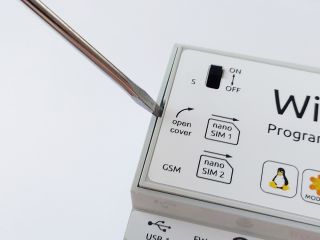
It is required to remove the controller cover to install the SIM card into the GSM module. The | It is required to remove the controller cover to install the SIM card into the GSM module. The lid is held on by four latches located on the sides of the lid. | ||
<div class="mw-translate-fuzzy"> | |||
'''Step 1'''. Lay the controller face up. | |||
</div> | |||
<div class="mw-translate-fuzzy"> | |||
<gallery mode="packed" heights="160px"> | <gallery mode="packed" heights="160px"> | ||
Image: Cover_rem1.jpg | | Image: Cover_rem1.jpg | Step 1 | ||
Image: Cover_rem2.jpg | | Image: Cover_rem2.jpg | Step 2 | ||
Image: Cover_rem3.jpg | | Image: Cover_rem3.jpg | Step 3 | ||
</gallery> | </gallery> | ||
</div> | |||
Версия 16:55, 17 августа 2022
Tools
To disassemble the controller, you will need a slotted screwdriver.
Disassembling
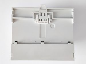
To disassemble the controller, you need to remove the back cover, which is held on by four latches, and extract the circuit board of controller from the case.
- Положите контроллер задней крышкой кверху.
- Вставьте отвертку между защелкой и основанием. Плавным вращательным движением отогните защелку и потяните заднюю крышку вверх. Проделайте тоже самое с остальными защелками.
- С помощью отвертки отогните оставшиеся защелки и снимите крышку.
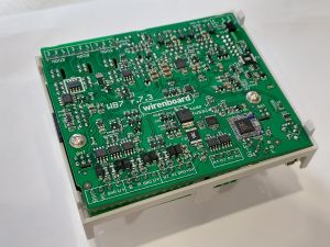
- Слегка отогните боковую стенку корпуса в месте, где расположен разъем для подключения внешних модулей, и вытолкните плату контроллера из корпуса. Не прилагайте больших усилий, чтобы не повредить разъем.
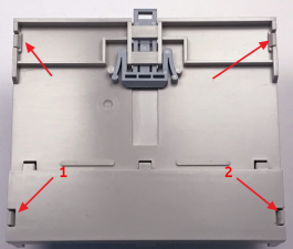
Step 1
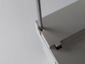
Step 2
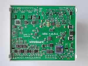
Step 3
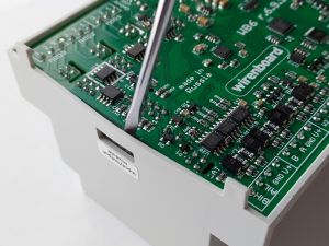
Step 4


Assembly
Assembly is carried out in the reverse order.
Step 1. Place the controller board in the case.
Step 1
Step 2
Step 3
Step 4


Cover removing
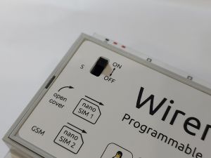
It is required to remove the controller cover to install the SIM card into the GSM module. The lid is held on by four latches located on the sides of the lid.
Step 1. Lay the controller face up.
Step 1
Step 2
Step 3


