Gas sensor WB-MSGR/en: различия между версиями
(Новая страница: «Before setting up the sensor, wait for the SE to enter the operating mode. The operating mode stabilizes the resistance of the SE under constant ambient condition…») |
Метка: ручная отмена |
||
| (не показана 21 промежуточная версия 3 участников) | |||
| Строка 142: | Строка 142: | ||
Before setting up the sensor, wait for the SE to enter the operating mode. The operating mode stabilizes the resistance of the SE under constant ambient conditions — under which the sensor will be constantly operated. | Before setting up the sensor, wait for the SE to enter the operating mode. The operating mode stabilizes the resistance of the SE under constant ambient conditions — under which the sensor will be constantly operated. | ||
The value of Rs0 depends on the type of sensor and can vary from one instance to another, so it is initially possible to set the value of Rs0 equal to the resistance after entering the operating mode. | |||
==== | ==== Automatic relay control ==== | ||
In modifications of sensors with relay the algorithm of its operation is as follows: if the value Rs/Rs0 ("Rs ratio") exceeds the set threshold "High threshold" (register 61), the relay <b>is disabled</b>. If the value becomes less than the "Low threshold" (register 62), the relay <b>is switched on</b>. | |||
For correct operation, the parameters "Rs ratio", "High threshold" and "Low threshold" must have values other than zero. | |||
=== | === Web-based management === | ||
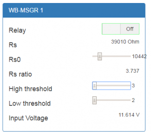
[[File:WB-MSGR-web.png |300px|thumb|right| | [[File:WB-MSGR-web.png |300px|thumb|right| WB-MSGR sensor in web interface]] | ||
The operation logic described above is implemented through settings that can be made in the sensor web interface. | |||
* Relay — | * Relay — relay status, can be changed manually. (For example, when a relay is triggered, you can first turn off the alarm and then address the problem) | ||
* Rs — | * Rs — current resistance of the sensing element. | ||
* Rs0 — | * Rs0 — resistance of the sensing element in the reference medium. | ||
* Rs ratio — | * Rs ratio — current RS/Rs0 ratio | ||
* High threshold - | * High — threshold turn-off threshold (see above) | ||
* Low threshold | * Low threshold — the threshold for inclusion (see above) | ||
* Input Voltage | * Input Voltage — the voltage supply of the sensor module | ||
=== | === Modbus register map === | ||
The set of registers differs from the set of registers of other modules due to the specifics of the device, we give it completely here. | |||
{| | {| border="1" class="wikitable" style="text-align:center" | ||
! | !Register / address | ||
! | !type | ||
! | !read-write | ||
! | !default | ||
! | !format | ||
! | !appointment | ||
! | !In modification | ||
|- | |- | ||
|8 | |8 | ||
| Строка 180: | Строка 180: | ||
|0 | |0 | ||
|seconds | |seconds | ||
| | |timeout for safe mode | ||
|<nowiki>-R</nowiki> | |<nowiki>-R</nowiki> | ||
|- | |- | ||
| Строка 195: | Строка 195: | ||
||R||-||raw_val * 16 | ||R||-||raw_val * 16 | ||
unsigned | unsigned | ||
|| | ||Raw averaged value with gas sensor ADC | ||
| | |all | ||
|- | |- | ||
|51 | |51 | ||
| Строка 202: | Строка 202: | ||
|R | |R | ||
|<nowiki>-</nowiki> | |<nowiki>-</nowiki> | ||
|R | |R × 0.1 (Ohm) | ||
unsigned | unsigned | ||
| | |The resistance value of the measuring element of the gas sensor | ||
| | | | ||
|- | |- | ||
| Строка 213: | Строка 213: | ||
|R/R0 * 1000 | |R/R0 * 1000 | ||
unsigned | unsigned | ||
| | |RS/Rs0 ratio (see register 60) | ||
| | | | ||
|- | |- | ||
| Строка 228: | Строка 228: | ||
|RW | |RW | ||
| | | | ||
|R | |R × 10 (Ohm) | ||
unsigned | unsigned | ||
| | |The resistance value Rs0 of the measuring element of the gas sensor at 100ppm for the registers 52 and 61-62 | ||
| | | | ||
|- | |- | ||
| Строка 239: | Строка 239: | ||
|R/R0 * 1000 | |R/R0 * 1000 | ||
unsigned | unsigned | ||
| | |Threshold for Rs/Rs0 (the rising edge, the threshold is exceeded) | ||
| | | | ||
|- | |- | ||
| Строка 248: | Строка 248: | ||
|R/R0 * 1000 | |R/R0 * 1000 | ||
unsigned | unsigned | ||
| | |Threshold for Rs/Rs0 (falling edge, falling below the threshold value) | ||
| | | | ||
|- | |- | ||
| Строка 259: | Строка 259: | ||
| | | | ||
|- | |- | ||
| 110 || holding || RW || 96 || | | 110 || holding || RW|| 96 || baud rate / 100 || RS-485 port speed, "'divided by 100"'. Permissible speeds: 1200, 2400, 4800, 9600, 19200, 38400, 57600, 115200 <br>([[UART_Communication_Settings|configure RS-485 communication parameters for wiren Board modbus devices]]) | ||
|colspan="3"| | |colspan="3"|all | ||
|- | |- | ||
| 111 || holding || RW || 0 || || | | 111 || holding || RW|| 0 || || configure the RS-485 port parity bit. Valid values: 0 - no parity bit (none), 1 - odd (odd), 2 - even (even) | | ||
|colspan="3"| | |colspan="3"|all | ||
|- | |- | ||
| 112 || holding || RW || 2 || || | | 112 || holding || RW|| 2 || || number of stop bits of RS-485 port. Valid values: 1, 2 | ||
|colspan="3"| | |colspan="3"|all | ||
|- | |- | ||
| | | | ||
| Строка 276: | Строка 276: | ||
| | | | ||
|- | |- | ||
| 120 (0x78) || holding || RW || 0 || | | 120 (0x78) || holding || RW|| 0 || 0 || write to the register causes a reboot of the MK stateless | ||
| | |everything | ||
|- | |- | ||
| 121 (0x79) || input || R || - || | | 121 (0x79) || input || R || - || mV || current supply voltage of the module | ||
| | |everything | ||
|- | |- | ||
| 128 (0x80) || holding || RW || 1 || || Modbus | | 128 (0x80) || holding || RW|| 1 || || Modbus device address | ||
| | |everything | ||
|- | |- | ||
| 200-206 || input || R || {'W','B','M','S','G','R'} || | | 200-206 || input || R || {'W','B','M','S','G','R'} | | | signature | ||
| | |everything | ||
|- | |- | ||
| 220-241 || input || R || || | | 220-241 || input || R | | | | _date__ _time__|| firmware build date | ||
| | |everything | ||
|- | |- | ||
|} | |} | ||
=== | ===Map of Coils === | ||
{| | {| border="1" class="wikitable" style="text-align:center" | ||
! | !Start address || Quantity || Destination | ||
! | !In modification | ||
|- | |- | ||
| 0 || 1 || style="text-align:left" | | | 0 || 1 || style="text-align:left" | relay Status (read and set) || -R | ||
|- | |- | ||
|} | |} | ||
== | ==Modbus Control== | ||
Details of the work with the module via Modbus Protocol is written in [[Sensors_Modbus_Management/en| Sensors Modbus Management ]]. | |||
You can also find a map of the device registers there. | |||
== | == Images and drawings of the device == | ||
{{Wbincludes:WBPicturesNoDrawing|1}} | {{Wbincludes:WBPicturesNoDrawing|1}} | ||
{{Wbincludes:WBPicturesNoDrawing|2}} | {{Wbincludes:WBPicturesNoDrawing|2}} | ||
Текущая версия на 11:24, 6 сентября 2022
The model is discontinued.
Purpose
Combined electrochemical gas sensors WB-MSGR with built-in relay.
Design: plastic housing with DIN rail mounting and mounting holes. Supply voltage 12 – 24V.
The module is controlled from the controller or PC via RS-485 bus by Modbus commands.
You can order a sensor with sensors to choose from:
- combustible gases: natural gas, methylpropane, propane, methane, hydrogen. Description: Файл:MQ2.pdf
- organic gases: NH3, NOx, alcohol, benzene, tobacco smoke, CO2. Description: Файл:SNS-MQ135.pdf
Modifications
Characteristics are coded in the article, according to the following scheme:
| Designation | Supported function |
|---|---|
| WB-MSGR-xxxx | version with built-in relay (basic model) |
| WB-MSG-xxxx | version without built-in relay (on request) |
Specifications
| Option | Value |
|---|---|
| Power | |
| Supply voltage | 12 V — 24 V DC |
| Power consumption |
|
| Terminals and wire section | |
| Recommended wire cross-section with NSUI, mm2 | 0,75 — 1 (2.5 for relay) |
| Length of the standard sleeve NSVE, mm | 8 |
| Torque of screws, N∙m | 0,2 (0,4 for relay) |
| Measured gas concentrations | |
| Sensitivity range |
|
| Outputs (in WB-MSGR MODEL) | |
| Relay output | Relay with common, normally open and normally closed contacts (SPDT). |
| Control | |
| Management interface | RS-485 |
| Interface isolation | Uninsulated |
| Communication protocol | Modbus RTU, address is set by software, factory settings are indicated on the label |
| RS-485 interface parameters |
speed 9600 bps; data bits 8; parity N; stop bits 2; Starting from firmware version 3.1.0 parameters interfaces can be configured programmatically:
|
| Ready for operation after power supply | see section #Principle of operation and setting sensor and gauge setup |
| dimensions | |
| Size | 65x46x29 mm |
| Width of DIN units | ~2.5 |
| operating Conditions | |
| Air temperature |
|
| Relative humidity | up to 98%, without condensation |
Installation
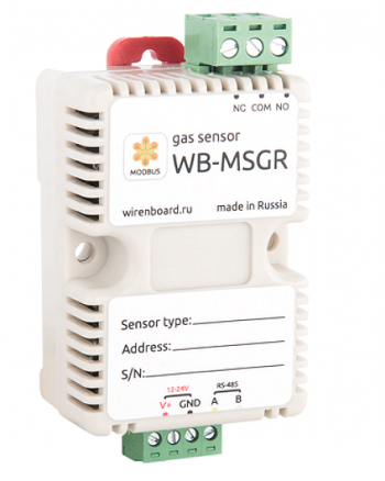
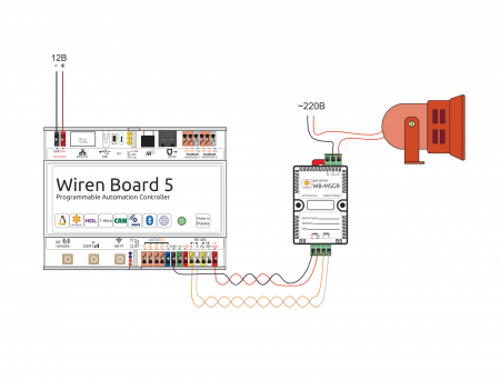
The sensor can be mounted on a standard 35 mm wide DIN rail and occupies a width of about 2.5 DIN modules. The sensor also has holes for direct attachment to any flat surface. The diameter of the holes — 4mm, the distance between the centers — 41 mm. the Distance between the head of the fixing screw and the surface (depth) — 11 mm. The module screw terminal block (see figure "WB-MSGR SENSOR") is used to connect power lines (V+ and GND) and control lines via RS-485 (RS-485 A and B). In the version with built-in relay, the upper screw terminals are connected to NC, COM, NO relay contacts.
Functions
Address change is broadcast (slave_id 0) team record (WRITE_SINGLE_REGISTER) to holding register with address 128 (0x80).
The 6-byte signature has address 200. The signature is unique for each device model and allows you to identify the model. To obtain the signatures, you should run READ_HOLDING_REGISTERS address 200 length 6. Writing to this area of memory is not supported and error 3 is returned when attempting to write to an invalid location.
Safe mode
In this mode, when the Modbus communication is terminated, the device disconnects the relay after a specified time.
To enable safe mode, write a value other than 0 to HOLDING_REGISTER at 8. This value is a timeout in seconds.
= = Operating principle and sensor setting ==
When the concentration of a certain gas changes, the resistance of the semiconductor sensing element (SE) of the Rs sensor changes. The measurements use the ratio of the resistance of the SE Rs to the resistance measured in the reference medium Rs0. As the concentration of gases to which the sensor is sensitive increases, the SE resistance decreases, respectively, the Rs/Rs0 Ratio decreases. Based on the value of the Rs/Rs0 ratio, a decision can be made to turn on the warning signal. For different gases, the same RS/Rs0 ratio corresponds to different concentrations of these gases in the environment.
There is a heater inside the sensor, which is constantly switched on, which makes it possible to measure the concentration of gases. If the sensor remained de-energized for a long time, then the output to the operating mode will require some time: from two days, if the sensor was not turned on for a month, to a week, if the sensor was not turned on for more than six months. Operation in an aggressive environment leads to degradation of SE, ice and condensate reduce its sensitivity.
Temperature and humidity also affect the resistance of the sensing element: it drops with increasing temperature and humidity.
Before setting up the sensor, wait for the SE to enter the operating mode. The operating mode stabilizes the resistance of the SE under constant ambient conditions — under which the sensor will be constantly operated.
The value of Rs0 depends on the type of sensor and can vary from one instance to another, so it is initially possible to set the value of Rs0 equal to the resistance after entering the operating mode.
Automatic relay control
In modifications of sensors with relay the algorithm of its operation is as follows: if the value Rs/Rs0 ("Rs ratio") exceeds the set threshold "High threshold" (register 61), the relay is disabled. If the value becomes less than the "Low threshold" (register 62), the relay is switched on.
For correct operation, the parameters "Rs ratio", "High threshold" and "Low threshold" must have values other than zero.
Web-based management
The operation logic described above is implemented through settings that can be made in the sensor web interface.
- Relay — relay status, can be changed manually. (For example, when a relay is triggered, you can first turn off the alarm and then address the problem)
- Rs — current resistance of the sensing element.
- Rs0 — resistance of the sensing element in the reference medium.
- Rs ratio — current RS/Rs0 ratio
- High — threshold turn-off threshold (see above)
- Low threshold — the threshold for inclusion (see above)
- Input Voltage — the voltage supply of the sensor module
Modbus register map
The set of registers differs from the set of registers of other modules due to the specifics of the device, we give it completely here.
| Register / address | type | read-write | default | format | appointment | In modification | ||
|---|---|---|---|---|---|---|---|---|
| 8 | holding | RW | 0 | seconds | timeout for safe mode | -R | ||
| 50 | input | R | - | raw_val * 16
unsigned |
Raw averaged value with gas sensor ADC | all | ||
| 51 | input | R | - | R × 0.1 (Ohm)
unsigned |
The resistance value of the measuring element of the gas sensor | |||
| 52 | input | R | R/R0 * 1000
unsigned |
RS/Rs0 ratio (see register 60) | ||||
| 60 | holding | RW | R × 10 (Ohm)
unsigned |
The resistance value Rs0 of the measuring element of the gas sensor at 100ppm for the registers 52 and 61-62 | ||||
| 61 | holding | RW | R/R0 * 1000
unsigned |
Threshold for Rs/Rs0 (the rising edge, the threshold is exceeded) | ||||
| 62 | holding | RW | R/R0 * 1000
unsigned |
Threshold for Rs/Rs0 (falling edge, falling below the threshold value) | ||||
| 110 | holding | RW | 96 | baud rate / 100 | RS-485 port speed, "'divided by 100"'. Permissible speeds: 1200, 2400, 4800, 9600, 19200, 38400, 57600, 115200 (configure RS-485 communication parameters for wiren Board modbus devices) |
all | ||
| 111 | holding | RW | 0 | all | ||||
| 112 | holding | RW | 2 | number of stop bits of RS-485 port. Valid values: 1, 2 | all | |||
| 120 (0x78) | holding | RW | 0 | 0 | write to the register causes a reboot of the MK stateless | everything | ||
| 121 (0x79) | input | R | - | mV | current supply voltage of the module | everything | ||
| 128 (0x80) | holding | RW | 1 | Modbus device address | everything | |||
| 200-206 | input | R | | | signature | everything | ||||
| 220-241 | input | | | | _date__ _time__ | firmware build date | everything | ||||
Map of Coils
| Start address | Quantity | Destination | In modification |
|---|---|---|---|
| 0 | 1 | relay Status (read and set) | -R |
Modbus Control
Details of the work with the module via Modbus Protocol is written in Sensors Modbus Management . You can also find a map of the device registers there.
Images and drawings of the device
По ссылкам ниже вы можете скачать изображения и чертежи устройства WB-MSGR-2-flammable.
Corel Draw 2018: WB-MSGR-2-flammable.cdr.zip
Corel Draw PDF: WB-MSGR-2-flammable.cdr.pdf
Autocad 2013 DXF: Мы еще не подготовили чертеж этого устройства. Вы можете запросить чертеж устройства "WB-MSGR gas sensor (flammable gases)" на портале техподдержки Wiren Board (необходима регистрация).
По ссылкам ниже вы можете скачать изображения и чертежи устройства WB-MSGR135-organic.
Corel Draw 2018: WB-MSGR135-organic.cdr.zip
Corel Draw PDF: WB-MSGR135-organic.cdr.pdf
Autocad 2013 DXF: Мы еще не подготовили чертеж этого устройства. Вы можете запросить чертеж устройства "WB-MSGR gas sensors (organic gases)" на портале техподдержки Wiren Board (необходима регистрация).


