Translations:Gas sensor WB-MSGR/12/en: различия между версиями

Материал из Wiren Board
(Новая страница: «== Installation== 200px|thumb|right|WB-MSGR MODULE Mounting dimensions File:Installation_WB5_+wb-msgr+syren.png|450px|thumb|left|Connect…»)
 
м (FuzzyBot переименовал страницу Translations:Датчик газа WB-MSGR/12/en в Translations:Gas sensor WB-MSGR/12/en без оставления перенаправления: Часть переводимой страницы Датчик газа WB-MSGR.)
 
(нет различий)

Текущая версия на 14:38, 2 августа 2022

Определение сообщения (Gas sensor WB-MSGR)
== Монтаж ==
[[Файл:WB-MS-dim.png|200px|thumb|right|Крепежные размеры модуля WB-MSGR]]
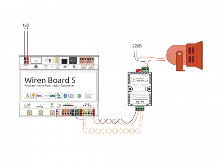
[[Файл:Installation_WB5_+wb-msgr+syren.png|450px|thumb|left|Подключение модуля WB-MSGR к контроллеру WB5. При превышении настроенной концентрации опасного газа срабатывает сирена]] 
Датчик может монтироваться на стандартную DIN-рейку шириной 35 мм. При этом он занимает пространство около 2,5 DIN-модуля. Датчик также имеет отверстия для непосредственного крепления к любой плоской поверхности. Диаметр отверстий — 4мм, расстояние между центрами — 41 мм. Расстояние между головкой крепежного винта и поверхностью (глубина) — 11 мм.
Блок винтовых зажимов модуля ([[#wbmsgrphoto|см. рисунок "Датчик WB-MSGR"]]) служит для подключения линий питания (V+ и GND), и линий управления по RS-485 (RS-485 A и B). В версии со встроенным реле верхние винтовые зажимы подключены к контактам реле NC, COM, NO.

Installation

WB-MSGR MODULE Mounting dimensions
Connect the WB-MSGR MODULE to the WB5 controller. If the configured concentration of the dangerous gas is exceeded, a siren is triggered.

The sensor can be mounted on a standard 35 mm wide DIN rail and occupies a width of about 2.5 DIN modules. The sensor also has holes for direct attachment to any flat surface. The diameter of the holes — 4mm, the distance between the centers — 41 mm. the Distance between the head of the fixing screw and the surface (depth) — 11 mm. The module screw terminal block (see figure "WB-MSGR SENSOR") is used to connect power lines (V+ and GND) and control lines via RS-485 (RS-485 A and B). In the version with built-in relay, the upper screw terminals are connected to NC, COM, NO relay contacts.