Модуль наличия напряжения (WBIO-DI-LVD-8)/en: различия между версиями
(Новая страница: «300px|thumb|right|Dimensions») |
|||
| (не показаны 4 промежуточные версии этого же участника) | |||
| Строка 72: | Строка 72: | ||
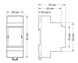
[[File:DIN 2U.png |300px|thumb|right|Dimensions]] | [[File:DIN 2U.png |300px|thumb|right|Dimensions]] | ||
== | == Connection to controller == | ||
See section [[Модули_ввода-вывода/en#Activating the modules in the controller web interface|activating the module in the web interface of the controller]]. | |||
== | == Connection == | ||
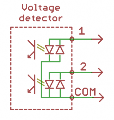
The voltage is applied to the COM terminal block and the corresponding module input. The inputs are separated by two isolated terminal groups: | |||
(1,2,3,4,COM,COM) | (1,2,3,4,COM,COM) and (COM, COM,5,6,7,8). Com terminals are common to a group of inputs. | ||
{| class="wikitable" | {| class="wikitable" | ||
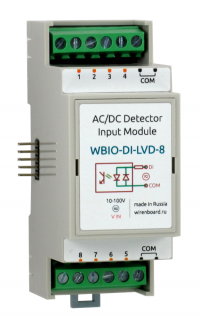
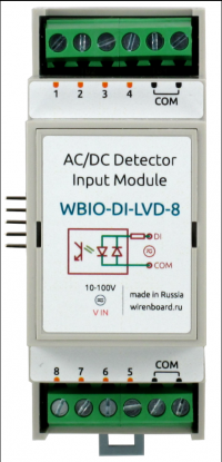
|[[ | |[[File:Wbio-di-lvd-8_front_view.png|200px|thumb|right|Wbio-DI-LVD-8 Pinout]] | ||
|[[ | |[[File:LVD-2.png|400px|thumb|none|WBIO-DI-LVD module wiring diagram]] | ||
|- | |- | ||
|} | |} | ||
== | == Device pictures and drawings == | ||
{{Wbincludes:WBPicturesNoDrawing|1}} | {{Wbincludes:WBPicturesNoDrawing|1}} | ||
Текущая версия на 13:24, 3 июля 2019
The model is discontinued. Recommended replacement is WBIO-DI-WD-14
Purpose
Input of discrete signals, control of circuit integrity, etc.
Technical specifications
Contains 8 inputs to determine the presence of voltage, both alternating (50Hz) and constant voltage of both polarities.
| Parameter | Value |
|---|---|
| Number of inputs | 8 |
| Isolated input groups | 2: [1 — 4] and [5 — 8] |
| Input type | voltage input |
| Operating voltage |
|
| Rated voltage | 12 — 24 V AC/DC |
| Maximum permissible voltage | 50 V AC/DC |
| Response time, not more than | 100 MS |
| Isolation voltage between input and controller | 5000 V (RMS.) |
| Module type | I (inverted addr.) |
| Maximum power consumption | 1 mW |
| Width, DIN units | 2 |
| Size | 36.3 x 90.2 x 57.5 mm |
| Terminals and wire section | |
|---|---|
| The recommended wire cross section with pin bushing insulated tip, mm2 | 2,5 |
| Standard sleeve length of pin bushing insulated tip, mm | 8 |
| Tightening torque of screws, Н∙м | 0,5 |
Connection to controller
See section activating the module in the web interface of the controller.
Connection
The voltage is applied to the COM terminal block and the corresponding module input. The inputs are separated by two isolated terminal groups: (1,2,3,4,COM,COM) and (COM, COM,5,6,7,8). Com terminals are common to a group of inputs.
Device pictures and drawings
По ссылкам ниже вы можете скачать изображения и чертежи устройства WBIO-DI-LVD-8.
Corel Draw 2018: WBIO-DI-LVD-8.cdr.zip
Corel Draw PDF: WBIO-DI-LVD-8.cdr.pdf
Autocad 2013 DXF: Мы еще не подготовили чертеж этого устройства. Вы можете запросить чертеж устройства "WBIO-DI-LVD-8 mo" на портале техподдержки Wiren Board (необходима регистрация).


