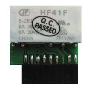
Модуль релейных выходов WBE-DO-R6C-1/en: различия между версиями
(Новая страница: «{| class="wikitable" !Terminal !Function |- |O1 |NO |- |O2 |NC |- |O3 |COM |}») |
(Новая страница: «The module is compatible with Wiren Board 5 controllers of all revisions. MOD1 or MOD2 slots are allowed for inserting the module.») |
||
| (не показано 10 промежуточных версий этого же участника) | |||
| Строка 30: | Строка 30: | ||
== | ==Configuration== | ||
Configuration is carried out in the web interface, section Configs => Hardware Modules Configuration. | |||
In the Internal slot 1 or 2 section (depending on the slot number) select "WBE-DO-R6C-1" and click Save. | |||
Once added, additional inputs appear in Devices next to the controller inputs. | |||
The device is detected immediately, no reboot is required. | |||
| Строка 44: | Строка 44: | ||
{| class="wikitable" | {| class="wikitable" | ||
! | !Slot | ||
! | !Channel | ||
! | !Topic | ||
|- | |- | ||
|MOD1 | |MOD1 | ||
| Строка 62: | Строка 62: | ||
== | ==Technical detail== | ||
The relay control signal is on the IRQ contact of the extension module | |||
=== | === Compatibility=== | ||
The module is compatible with [[Wiren Board 5/en|Wiren Board 5]] controllers of all revisions. MOD1 or MOD2 slots are allowed for inserting the module. | |||
Текущая версия на 19:22, 1 июля 2019
The module has one SPDT configuration relay (switch contact).
Max current: 6A for 230V AC or 30V DC. The maximum current is specified for the resistive load.
Pinout:
| Terminal | Function |
|---|---|
| O1 | NO |
| O2 | NC |
| O3 | COM |
Configuration
Configuration is carried out in the web interface, section Configs => Hardware Modules Configuration.
In the Internal slot 1 or 2 section (depending on the slot number) select "WBE-DO-R6C-1" and click Save.
Once added, additional inputs appear in Devices next to the controller inputs.
The device is detected immediately, no reboot is required.
MQTT
| Slot | Channel | Topic |
|---|---|---|
| MOD1 | wb-gpio/MOD1_OUT1 | /devices/wb-gpio/controls/MOD1_OUT1 |
| MOD2 | wb-gpio/MOD2_OUT1 | /devices/wb-gpio/controls/MOD2_OUT1 |
Technical detail
The relay control signal is on the IRQ contact of the extension module
Compatibility
The module is compatible with Wiren Board 5 controllers of all revisions. MOD1 or MOD2 slots are allowed for inserting the module.

