Первое включение Wiren Board/en: различия между версиями
(Новая страница: «thumb|300px|wifi antenna Connection thumb|300px|Connecting GPS and GSM antennas File:Map Connector.JPG|thumb…») |
|||
| (не показано 18 промежуточных версий этого же участника) | |||
| Строка 2: | Строка 2: | ||
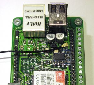
[[File:Antenna Wi-fi.JPG|thumb|300px|wifi antenna Connection]] | [[File:Antenna Wi-fi.JPG|thumb|300px|wifi antenna Connection]] | ||
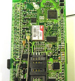
[[File:Antenna GPS.JPG|thumb|300px|Connecting GPS and GSM antennas]] | [[File:Antenna GPS.JPG|thumb|300px|Connecting GPS and GSM antennas]] | ||
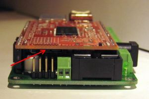
[[File: | [[File:Разъем_карты.JPG|thumb|300px|Memory card slot]] | ||
=== Antenna connection === | === Antenna connection === | ||
Connector u.fl for WiFi is inside the Wiren Board. | |||
For connecting the antenna you need to remove the red charge, and a light press until it clicks to put the corresponding connector (it is convenient to do that with a pencil). | |||
Antennas for GPS and GSM are connected from the outside of the board. | |||
''' | '''Do not place the GSM antenna near the processor.''' Aiming at the quartz of the processor causes it to reboot. Turn the antenna away from the USB and Ethernet connectors (as on the photo). | ||
=== | === Flash card === | ||
[[Создание microSD-карты с образом| | [[Создание microSD-карты с образом/en|Create a microSD card with the image]]. | ||
Insert into the connector (on the side of the OLinuXino-MICRO Board). | |||
=== | === Power Supply === | ||
Connect the external power supply to the power jack. | |||
Or supply power to terminals 17 (Vin) and 18 (GND). | |||
Permissible voltage range - 5-22 V. | |||
=== Debug UART === | === Debug UART === | ||
See [[WB_Debug_Console/en | here ]]. | |||
For Windows users: download [http://www.chiark.greenend.org.uk/~sgtatham/putty/download.html Putty ] and run it. | |||
In the settings, specify the connection type - serial, speed - 115200, line - COM3 (usually COM3, otherwise see the device Manager list of ports). | |||
[[Файл:Настройки_Путти.jpg |thumb|300px| | [[Файл:Настройки_Путти.jpg |thumb|300px| Putty settings]] | ||
Connect the USB-UART adapter. Open the session. | |||
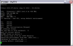
Now when you turn on the WirenBoard should immediately display the Linux console at boot. | |||
[[ | [[File:Консоль.JPG |thumb|300px| Console at boot]] | ||
If this does not happen, you may have confused Rx and Tx. Or for any other reason. | |||
Текущая версия на 18:26, 27 ноября 2019
Antenna connection
Connector u.fl for WiFi is inside the Wiren Board.
For connecting the antenna you need to remove the red charge, and a light press until it clicks to put the corresponding connector (it is convenient to do that with a pencil).
Antennas for GPS and GSM are connected from the outside of the board.
Do not place the GSM antenna near the processor. Aiming at the quartz of the processor causes it to reboot. Turn the antenna away from the USB and Ethernet connectors (as on the photo).
Flash card
Create a microSD card with the image.
Insert into the connector (on the side of the OLinuXino-MICRO Board).
Power Supply
Connect the external power supply to the power jack. Or supply power to terminals 17 (Vin) and 18 (GND). Permissible voltage range - 5-22 V.
Debug UART
See here .
For Windows users: download Putty and run it.
In the settings, specify the connection type - serial, speed - 115200, line - COM3 (usually COM3, otherwise see the device Manager list of ports).
Connect the USB-UART adapter. Open the session.
Now when you turn on the WirenBoard should immediately display the Linux console at boot.
If this does not happen, you may have confused Rx and Tx. Or for any other reason.


