Управление низковольтной нагрузкой/en: различия между версиями
(Новая страница: «thumb|400px|Equivalent Ax output circuit for WB4 controller To reduce the total number of terminals, the low-voltage load control channels are com…») |
(Новая страница: «'''Note for Wiren Board versions 2.8 and 3.5:''' * when connecting inductive loads (relay) do not forget to put a protective diode - a surge of voltage from the r…») |
||
| Строка 11: | Строка 11: | ||
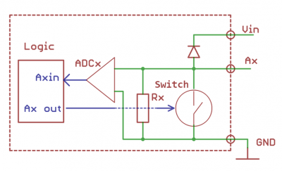
To reduce the total number of terminals, the low-voltage load control channels are combined with ADC channels - see[[Мультиплексирование портов/en |Multiplexing ports]]. Therefore, the outputs have a large, but the final resistance (30-100k). This can cause, for example, a weak glow of led strips ''(The solution is: add a resistor to the power supply)''. | To reduce the total number of terminals, the low-voltage load control channels are combined with ADC channels - see[[Мультиплексирование портов/en |Multiplexing ports]]. Therefore, the outputs have a large, but the final resistance (30-100k). This can cause, for example, a weak glow of led strips ''(The solution is: add a resistor to the power supply)''. | ||
''' | '''Note for Wiren Board versions 2.8 and 3.5:''' | ||
* | * when connecting inductive loads (relay) do not forget to put a protective diode - a surge of voltage from the relay coil can damage the controller. Maximum current per channel - 3A, voltage up to 24V. | ||
''' | '''Note for Wiren Board version 4:''' | ||
A protective diode is built-in in Wiren Board 4 controller and the maximum voltage must not exceed the controller supply voltage (Vin). The maximum current is also 3 A. If multiple channels are used and '''the total current is greater than 5 A, connect multiple GND terminals to the "minus" of the power supply.''' | |||
Версия 17:37, 16 мая 2019
There are the so-called "transistor outputs", also FET, to control the low-voltage load (with voltage up to the input voltage) in the Wiren Board controllers. They can control the switching of low-voltage lamps, led strips, external relay blocks, etc.
All transistor outputs can be controlled from the web interface, where they are called according to the terminals, for example A1_OUT.
Technical detail
To reduce the total number of terminals, the low-voltage load control channels are combined with ADC channels - seeMultiplexing ports. Therefore, the outputs have a large, but the final resistance (30-100k). This can cause, for example, a weak glow of led strips (The solution is: add a resistor to the power supply).
Note for Wiren Board versions 2.8 and 3.5:
- when connecting inductive loads (relay) do not forget to put a protective diode - a surge of voltage from the relay coil can damage the controller. Maximum current per channel - 3A, voltage up to 24V.
Note for Wiren Board version 4: A protective diode is built-in in Wiren Board 4 controller and the maximum voltage must not exceed the controller supply voltage (Vin). The maximum current is also 3 A. If multiple channels are used and the total current is greater than 5 A, connect multiple GND terminals to the "minus" of the power supply.
Примеры использования
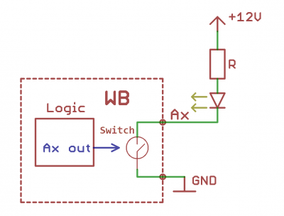
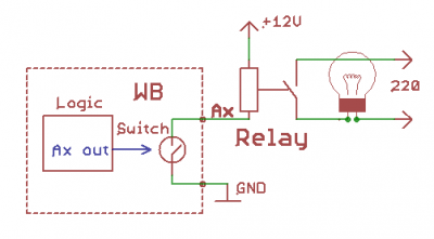
Нагрузка подключается следующим образом: "плюс" нагрузки подключается к источнику питания, "минус" подключается к транзисторному выходу. Чтобы нагрузка начала работать, нужно подать высокий уровень на затвор транзистора.
На иллюстрациях приведены схемы подключения светодиода и реле.
Также можно легко подключить готовый модуль реле, например такой
Пример работы в Linux
Смотрите GPIO.
- Находим номер GPIO, соответсвующий нужному клеммнику в таблице WB2.8/WB3.5/WB4/WB5. Для клеммника номер 2 в версии 2,8 это GPIO 32.
- Экспортируем GPIO в sysfs
root@wirenboard:~# echo 32 > /sys/class/gpio/export
- Устанавливаем GPIO в режим вывода для управления транзистором. Это обязательно, т.к. GPIO может находится в режиме ввода и иметь высокий импенданс, оставляя транзистор в неопределённом состоянии.
root@wirenboard:~# echo out > /sys/class/gpio/gpio32/direction
- Открываем транзистор, подавая логический высокий уровень на затвор:
root@wirenboard:~# echo 1 > /sys/class/gpio/gpio32/value
- Закрываем транзистор, подавая логический ноль на затвор:
root@wirenboard:~# echo 0 > /sys/class/gpio/gpio32/value


