Управление низковольтной нагрузкой/en: различия между версиями
(Новая страница: «==Technical detail==») |
|||
| (не показано 10 промежуточных версий этого же участника) | |||
| Строка 8: | Строка 8: | ||
==Technical detail== | ==Technical detail== | ||
[[File:Ax.png|thumb|400px| | [[File:Ax.png|thumb|400px|Equivalent Ax output circuit for WB4 controller]] | ||
To reduce the total number of terminals, the low-voltage load control channels are combined with ADC channels - see[[Мультиплексирование портов/en |Multiplexing ports]]. Therefore, the outputs have a large, but the final resistance (30-100k). This can cause, for example, a weak glow of led strips ''(The solution is: add a resistor to the power supply)''. | |||
''' | '''Note for Wiren Board versions 2.8 and 3.5:''' | ||
* | * when connecting inductive loads (relay) do not forget to put a protective diode - a surge of voltage from the relay coil can damage the controller. Maximum current per channel - 3A, voltage up to 24V. | ||
''' | '''Note for Wiren Board version 4:''' | ||
A protective diode is built-in in Wiren Board 4 controller and the maximum voltage must not exceed the controller supply voltage (Vin). The maximum current is also 3 A. If multiple channels are used and '''the total current is greater than 5 A, connect multiple GND terminals to the "minus" of the power supply.''' | |||
== | ==The examples of use== | ||
[[File:Led.png|thumb|400px| | [[File:Led.png|thumb|400px|Led connection example]] | ||
[[File:Relay.png|thumb|400px| | [[File:Relay.png|thumb|400px|Relay connection example]] | ||
The load is connected as follows: "plus" load is connected to the power supply, "minus" is connected to the transistor output. For the load to start working, you need to apply a high level to the gate of the transistor. | |||
The illustrations show the wiring diagrams of the led and relay. | |||
You can also easily connect a ready relay module, [http://dx.com/p/4-channel-5v-relay-module-black-blue-171144 such as] | |||
== | ==The example of work in Linux== | ||
See [[GPIO/en|GPIO]]. | |||
# | # Find the GPIO number corresponding to the desired terminal in the table[[Список GPIO/en|WB2.8]]/[[WB SH 3.5: Список GPIO/en|WB3.5]]/[[Wiren Board 4: Список GPIO/en|WB4]]/[[Wiren Board 5:Список GPIO|WB5]]. For terminal strip number 2 in version 2.8, it is GPIO 32. | ||
# | # Export GPIO to sysfs | ||
#:<pre>root@wirenboard:~# echo 32 > /sys/class/gpio/export</pre> | #:<pre>root@wirenboard:~# echo 32 > /sys/class/gpio/export</pre> | ||
# | # Set the GPIO to output mode to control the transistor. This is required because GPIO can be in input mode and have a high impedance, leaving the transistor in an undefined state. | ||
#:<pre>root@wirenboard:~# echo out > /sys/class/gpio/gpio32/direction</pre> | #:<pre>root@wirenboard:~# echo out > /sys/class/gpio/gpio32/direction</pre> | ||
# | # Open the transistor, giving a logical high level to the gate: | ||
#:<pre>root@wirenboard:~# echo 1 > /sys/class/gpio/gpio32/value</pre> | #:<pre>root@wirenboard:~# echo 1 > /sys/class/gpio/gpio32/value</pre> | ||
# | # Close the transistor, giving a logical zero to the gate: | ||
#:<pre>root@wirenboard:~# echo 0 > /sys/class/gpio/gpio32/value</pre> | #:<pre>root@wirenboard:~# echo 0 > /sys/class/gpio/gpio32/value</pre> | ||
Текущая версия на 19:14, 16 мая 2019
There are the so-called "transistor outputs", also FET, to control the low-voltage load (with voltage up to the input voltage) in the Wiren Board controllers. They can control the switching of low-voltage lamps, led strips, external relay blocks, etc.
All transistor outputs can be controlled from the web interface, where they are called according to the terminals, for example A1_OUT.
Technical detail
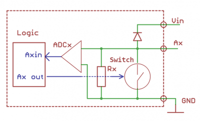
To reduce the total number of terminals, the low-voltage load control channels are combined with ADC channels - seeMultiplexing ports. Therefore, the outputs have a large, but the final resistance (30-100k). This can cause, for example, a weak glow of led strips (The solution is: add a resistor to the power supply).
Note for Wiren Board versions 2.8 and 3.5:
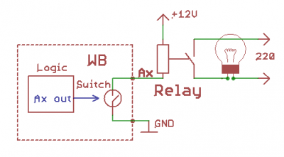
- when connecting inductive loads (relay) do not forget to put a protective diode - a surge of voltage from the relay coil can damage the controller. Maximum current per channel - 3A, voltage up to 24V.
Note for Wiren Board version 4: A protective diode is built-in in Wiren Board 4 controller and the maximum voltage must not exceed the controller supply voltage (Vin). The maximum current is also 3 A. If multiple channels are used and the total current is greater than 5 A, connect multiple GND terminals to the "minus" of the power supply.
The examples of use
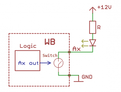
The load is connected as follows: "plus" load is connected to the power supply, "minus" is connected to the transistor output. For the load to start working, you need to apply a high level to the gate of the transistor.
The illustrations show the wiring diagrams of the led and relay.
You can also easily connect a ready relay module, such as
The example of work in Linux
See GPIO.
- Find the GPIO number corresponding to the desired terminal in the tableWB2.8/WB3.5/WB4/WB5. For terminal strip number 2 in version 2.8, it is GPIO 32.
- Export GPIO to sysfs
root@wirenboard:~# echo 32 > /sys/class/gpio/export
- Set the GPIO to output mode to control the transistor. This is required because GPIO can be in input mode and have a high impedance, leaving the transistor in an undefined state.
root@wirenboard:~# echo out > /sys/class/gpio/gpio32/direction
- Open the transistor, giving a logical high level to the gate:
root@wirenboard:~# echo 1 > /sys/class/gpio/gpio32/value
- Close the transistor, giving a logical zero to the gate:
root@wirenboard:~# echo 0 > /sys/class/gpio/gpio32/value


