ADC/en: различия между версиями

Материал из Wiren Board
(Новая страница: «Wiren Board сontrollers versions 2.3 and 4 have 8 ADC channels that are multiplexed into one processor channel (LRADC1). Multiplexing channels are shown in the t…»)
 
(не показано 45 промежуточных версий 4 участников)
Строка 1: Строка 1:
<languages/>
<languages/>{{DISPLAYTITLE: Analog inputs (ADC)}}
== Definitions ==
'''Analog to digital converters (ADC)''' — devices designed to convert input analog signals into digital code.


== How to get voltage from ADC ==
'''Analog inputs''' — ADC inputs used to measure the voltage applied to them. Analog inputs in automation devices are designed to connect sensors with an [[AnalogSensors_connecting | analog output signal]].


#Select the terminal to which your source can be connected based on the maximum allowable voltage (see table below).
== Analog inputs in the Wiren Board controller==
#Most ADC terminals have two functions: ADC and low-voltage load control. Before measuring the voltage on the ADC, turn off the appropriate low-voltage load control output. For example, if you are connecting to terminal A1, turn off A1_OUT in the web interface (the Relays & FETs section).
=== Wiren Board 6 === 
#:For details, see [[Multiplexing ports|Multiplexing ports]]
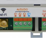
In the Wiren Board 6 ADC processor chanels are connected to terminals A1-A4. Also, the ADC has an input voltage (after the input diodes) and a voltage at the 5Vout terminal.
#Connect your source to the terminal. The voltage value will immediately appear in the [[Wiren Board 4:Веб-интерфейс | веб-интерфейсе]] in the ADCs device. The value is also translated to the MQTT message system[[MQTT|MQTT]].
=== Wiren Board 7 === 
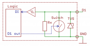
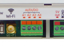
In the Wiren Board 7 processor chanels are connected to terminals A1-A3. Voltages at the D1 terminal and at the 5Vout terminal are not measured.
<gallery mode="packed" heights="100px" caption="Universal inputs/outputs">
Image: WB6_AI_DI.PNG| Wiren Board 6
Image: WB7_AI_DI.PNG| Wiren Board 7
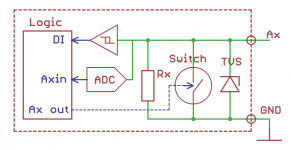
Image: WB6.Ax.png| Schematic diagram of the input Ax
Image: WB7.D1.png| Schematic diagram of the input D1 in Wiren Board 7
</gallery>
== Voltage measurement ==
=== Connection and setup ===
#The voltage must be within the acceptable range.
#The Ax terminal blocks perform two functions: ADC and low voltage load control. Before measuring voltage, set the corresponding low voltage load control output to the off position. For example, if you are connecting to terminal A1, turn off A1_OUT in [[Веб-интерфейс Wiren Board | web interface]] (section Relays & FETs).
#Connect your source to the Ax terminal. The voltage value will immediately appear in the [[Веб-интерфейс Wiren Board | web interface]] on the ADCs. The value is also transmitted to the message system [[Special:MyLanguage/MQTT|MQTT]].
=== Measured voltage display  === 
The wb-homa-adc daemon transmits a value to MQTT message queuing to the /devices/wb-adc/controls/Vin topic.
So the value is displayed in the web interface as the Vin channel of the ADC device.


Смотрите также:
== Using values from external programs ==
* [[Wiren Board 6.2: Peripherals#Каналы АЦП| ADC chanels of Wiren Board 6.2]]
 
* [[Wiren_Board_7.2:_Peripherals#Аналоговые_входы| ADC chanels of Wiren Board 7]]
A special WB-homa-adc driver translates the value to the [[MQTT|MQTT]] system and can be obtained there.
* [[ADC.OLD | ADC lists for older controller versions]]
 
Also, the value can be obtained in manual mode:[[Низкоуровневая работа с ADC|Низкоуровневая работа с ADC]].
 
 
== Resistance measurement ==
 
Wiren Board 5.8 controllers '''and below''' were able to measure the resistance of resistors connected to the R1 and R2 inputs.
 
TODO: you should write here how to configure resistive inputs through the web interface.
 
See [[ADC:Измерение сопротивлений - технические детали|ADC:Измерение сопротивлений - технические детали]]
 
 
== Input voltage  ==
 
Демон wb-homa-adc транслирует значение в очередь сообщений MQQT в топик  /devices/wb-adc/controls/Vin .
Таким образом, значение отображается в веб-интерфейсе как канал Vin устройства ADCs
 
The wb-homa-adc daemon translates the value to the MQQT message queue in the /devices/wb-adc/controls/Vin topic. Therefore, the value is displayed in the web interface as the Vin channel of the ADCs device
 
 
== Battery voltage ==
 
The wb-homa-adc daemon translates the value to the MQTT message queue in the topic /devices/wb-adc/controls/BAT. Therefore, the value is displayed in the web interface as the BAT channel of the ADCs device
 
 
Manual mode: see [[Низкоуровневая работа с ADC| low-Level ADC operation]].


== Technical details on the implementation of the ADC ==
 
Wiren Board сontrollers versions 2.3 and 4 have 8 ADC channels that are multiplexed into one processor channel (LRADC1). Multiplexing channels are shown in the table [[Wiren Board 4:Список GPIO|Wiren Board 4:Список GPIO]].
 
Wiren Board 5 использует 8 различных каналов АЦП, которые подключены к отдельным каналам процессора. Линия 4В подключена к каналу BAT (LRADC7), кроме этого измеряется
напряжение на 2-х резистивных входах, 4 универсальных входах A1-A4 и входное напряжение (см. таблицу ниже).
 
Каналы ADC, обслуживающие входы R1 и R2 имеют встроенный независимый источник тока, который используется для измерения сопротивления, подключенного к каналу.
Точность источника тока: 5%. См. [[Special:MyLanguage/Калибровка аналоговых входов|Калибровка аналоговых входов]].
 
В Wiren Board 6 каналы АЦП процессора подключены к клеммникам A1-A4. Также на АЦП заведено входное напряжение (после входных диодов) и напряжение на клемме 5Vout.


=== Основные каналы===
 
Часть каналов АЦП выведена на клеммы параллельно с транзисторами управления низковольтной нагрузки. '''Убедитесь''', что вы явно закрыли соответствующий FET помощью GPIO перед использованием АЦП. Подробнее смотрите [[Special:MyLanguage/Мультиплексирование портов|Мультиплексирование портов]]
 
 
=== Списки АЦП для разных устройств ===
 
 
==== Wiren Board 6 ====
 
См.  [[Wiren Board 6.2: Peripherals#Каналы АЦП|Wiren Board 6.2: Peripherals#Каналы АЦП]]
 
 
==== Wiren Board 5 ====
 
{|  border="1"  class="wikitable" style="text-align:center"
! клеммник || Канал АЦП (LRADCxx) || Делитель||  Итоговая формула (без делителя) || V макс. измеряемое || комментарии
|-
 
| A1 ||  1
|rowspan="4"|88k7/12k  ||  rowspan="4"|  V = N * 3.80 mV || rowspan="4"| 31V || rowspan="4"|
|-
| A2 || 2
|-
| A3 || 3 
|-
| A4 || 4 
|-
 
 
| R1 ||  6
|rowspan="2"| 1  ||  rowspan="2"|  V = N * 0.4518 mV|| rowspan="2"| 3.1V || rowspan="2"|  r2 = 3150 Ohm,
r1 = 1000 kOhm
|-
| R2 || 0 
|-


| 4В/li_pol || 7 ||
| V = N * 1.807 mV || - || на линии 4 В
|-
| Vin || 5
|88k7/12k||  V = N * 3.80 mV || 31V || входное напряжение
|-
|}
 
 
==== WB4 ====
 
{| border="1"
| клеммник || Делитель || Формула для пересчета  || Итоговая формула (без делителя) || V макс. измеряемое (с делителем)  || комментарии
|-
 
| A1-A3 || 100k/90.9k || N / 4095 * 1.85V * 2.100 || V = N * 0.949 mV || 7.4V  ||
|-
| A4-A5 || 100k/11.86k ||  N / 4095 * 1.85V * 9.43  || V = N * 4.26 mV || 34.4V ||
|-
| R1-R2 || 3k15/1M || N / 4095 * 1.85V * 1.003 || V = N * 0.426 mV || 3.7V ||
|-
| li_pol || 100k/90.9k || N / 4095 * 1.85V * 2.100  || V = N * 0.949 mV || - || на аккумуляторе
|-
 
| Vin || 33k/4k51 ||N / 4095 * 1.85V * 8.32 || V = N * 3.76 mV || 30.6V || входное напряжение, iio channel 0
|-
 
|}
 
 
==== WB3.5 ====
 
{| border="1"
| клеммник || Делитель|| Формула для пересчета || Итоговая формула || V max || комментарии
|-
 
| A1-A4 || 220k/22k||  V = N / 4095 * 1.85V * 11 || V = N * 4.97 mV || ||
|-
 
| R1-R4 || - ||  V = N / 4095 * 1.85V ||V = N * 0.452 mV || ||
|-
 
| Vin || 33k/4k53 ||N / 4095 * 1.85V * 8.28 || V = N * 3.74 mV || 30V || входное напряжение, iio channel: 0
|-
 
|}


==== WB NETMON-1 ====
 
{| border="1"
| клеммник || Делитель || Формула для пересчета  || Итоговая формула (без делителя) || V макс. измеряемое (с делителем)  || комментарии
|-
| A1-A8 || 31k/4.68k || N / 4095 * 1.85V * 7.627 || V = N * 3.446 mV || 20V ||
|-
| Vin || 12k/1k ||N / 4095 * 1.85V * 13 || V = N * 5.873 mV ||  || входное напряжение
|-
|}


==== WB2.8 ====
 
{| border="1"
| клеммник || Делитель|| Формула для пересчета  || Итоговая формула || комментарии
|-
 
| A1-A7 || 12K/33K||  V = N / 4095 * 1.85V * 1.364 || V = N * 0.616 mV ||
|-
 
|}

Текущая версия на 11:18, 23 сентября 2022

Другие языки:

Definitions

Analog to digital converters (ADC) — devices designed to convert input analog signals into digital code.

Analog inputs — ADC inputs used to measure the voltage applied to them. Analog inputs in automation devices are designed to connect sensors with an analog output signal.

Analog inputs in the Wiren Board controller

Wiren Board 6

In the Wiren Board 6 ADC processor chanels are connected to terminals A1-A4. Also, the ADC has an input voltage (after the input diodes) and a voltage at the 5Vout terminal.

Wiren Board 7

In the Wiren Board 7 processor chanels are connected to terminals A1-A3. Voltages at the D1 terminal and at the 5Vout terminal are not measured.

Voltage measurement

Connection and setup

  1. The voltage must be within the acceptable range.
  2. The Ax terminal blocks perform two functions: ADC and low voltage load control. Before measuring voltage, set the corresponding low voltage load control output to the off position. For example, if you are connecting to terminal A1, turn off A1_OUT in web interface (section Relays & FETs).
  3. Connect your source to the Ax terminal. The voltage value will immediately appear in the web interface on the ADCs. The value is also transmitted to the message system MQTT.

Measured voltage display

The wb-homa-adc daemon transmits a value to MQTT message queuing to the /devices/wb-adc/controls/Vin topic. So the value is displayed in the web interface as the Vin channel of the ADC device.

Смотрите также: