ADC/en: различия между версиями
Matveevrj (обсуждение | вклад) (Новая страница: «Смотрите также: * ADC chanels of Wiren Board 6.2 * ADC chanels of Wiren Board 7 * ADC lists for older controller versions») |
Matveevrj (обсуждение | вклад) |
||
| (не показано 9 промежуточных версий этого же участника) | |||
| Строка 1: | Строка 1: | ||
<languages/>{{DISPLAYTITLE: Analog inputs (ADC)}} | <languages/>{{DISPLAYTITLE: Analog inputs (ADC)}} | ||
== | == Definitions == | ||
'''Analog to digital converters (ADC)''' — devices designed to convert input analog signals into digital code. | '''Analog to digital converters (ADC)''' — devices designed to convert input analog signals into digital code. | ||
| Строка 7: | Строка 7: | ||
== Analog inputs in the Wiren Board controller== | == Analog inputs in the Wiren Board controller== | ||
=== Wiren Board 6 === | === Wiren Board 6 === | ||
In Wiren Board 6 ADC processor chanels are connected to terminals A1-A4. Also, the ADC has an input voltage (after the input diodes) and a voltage at the 5Vout terminal. | In the Wiren Board 6 ADC processor chanels are connected to terminals A1-A4. Also, the ADC has an input voltage (after the input diodes) and a voltage at the 5Vout terminal. | ||
=== Wiren Board 7 === | === Wiren Board 7 === | ||
In Wiren Board 7 processor chanels are connected to terminals A1-A3. Voltages at the D1 terminal and at the 5Vout terminal are not measured. | In the Wiren Board 7 processor chanels are connected to terminals A1-A3. Voltages at the D1 terminal and at the 5Vout terminal are not measured. | ||
<gallery mode="packed" heights="100px" caption="Universal inputs/outputs"> | <gallery mode="packed" heights="100px" caption="Universal inputs/outputs"> | ||
Image: WB6_AI_DI.PNG| Wiren Board 6 | Image: WB6_AI_DI.PNG| Wiren Board 6 | ||
Image: WB7_AI_DI.PNG| Wiren Board 7 | Image: WB7_AI_DI.PNG| Wiren Board 7 | ||
Image: WB6.Ax.png| Schematic of the Ax | Image: WB6.Ax.png| Schematic diagram of the input Ax | ||
Image: WB7.D1.png| Schematic of the D1 in Wiren Board 7 | Image: WB7.D1.png| Schematic diagram of the input D1 in Wiren Board 7 | ||
</gallery> | </gallery> | ||
== Voltage measurement == | == Voltage measurement == | ||
=== Connection and setup === | === Connection and setup === | ||
#The voltage must be within the acceptable range. | #The voltage must be within the acceptable range. | ||
#The Ax terminal blocks perform two functions: ADC and low voltage load control. Before measuring voltage, set the corresponding low voltage load control output to the off position. For example, if you are connecting to terminal A1, turn off in [[Веб-интерфейс Wiren Board | web interface]] | #The Ax terminal blocks perform two functions: ADC and low voltage load control. Before measuring voltage, set the corresponding low voltage load control output to the off position. For example, if you are connecting to terminal A1, turn off A1_OUT in [[Веб-интерфейс Wiren Board | web interface]] (section Relays & FETs). | ||
#Connect your source to the Ax terminal. The voltage value will immediately appear in the [[Веб-интерфейс Wiren Board | web interface]] on the ADCs. The value is also | #Connect your source to the Ax terminal. The voltage value will immediately appear in the [[Веб-интерфейс Wiren Board | web interface]] on the ADCs. The value is also transmitted to the message system [[Special:MyLanguage/MQTT|MQTT]]. | ||
=== Measured voltage display === | === Measured voltage display === | ||
The wb-homa-adc daemon | The wb-homa-adc daemon transmits a value to MQTT message queuing to the /devices/wb-adc/controls/Vin topic. | ||
So the value is displayed in the web interface as the Vin channel of the ADC device. | So the value is displayed in the web interface as the Vin channel of the ADC device. | ||
Текущая версия на 11:18, 23 сентября 2022
Definitions
Analog to digital converters (ADC) — devices designed to convert input analog signals into digital code.
Analog inputs — ADC inputs used to measure the voltage applied to them. Analog inputs in automation devices are designed to connect sensors with an analog output signal.
Analog inputs in the Wiren Board controller
Wiren Board 6
In the Wiren Board 6 ADC processor chanels are connected to terminals A1-A4. Also, the ADC has an input voltage (after the input diodes) and a voltage at the 5Vout terminal.
Wiren Board 7
In the Wiren Board 7 processor chanels are connected to terminals A1-A3. Voltages at the D1 terminal and at the 5Vout terminal are not measured.
- Universal inputs/outputs
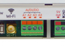
Wiren Board 6
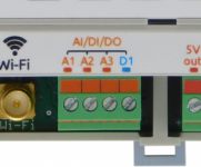
Wiren Board 7
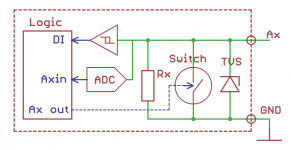
Schematic diagram of the input Ax
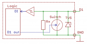
Schematic diagram of the input D1 in Wiren Board 7


Voltage measurement
Connection and setup
- The voltage must be within the acceptable range.
- The Ax terminal blocks perform two functions: ADC and low voltage load control. Before measuring voltage, set the corresponding low voltage load control output to the off position. For example, if you are connecting to terminal A1, turn off A1_OUT in web interface (section Relays & FETs).
- Connect your source to the Ax terminal. The voltage value will immediately appear in the web interface on the ADCs. The value is also transmitted to the message system MQTT.
Measured voltage display
The wb-homa-adc daemon transmits a value to MQTT message queuing to the /devices/wb-adc/controls/Vin topic. So the value is displayed in the web interface as the Vin channel of the ADC device.
Смотрите также: