Disassembling the controller case/en: различия между версиями
Matveevrj (обсуждение | вклад) (Новая страница: «'''Step 2'''. Make sure the '''On/Off''' switch on the front panel is in its aperture. Do not apply excessive force to avoid damaging the switch.») |
Matveevrj (обсуждение | вклад) (Новая страница: «'''Step 3'''. Easily bend the side wall near the connector housing for connecting side modules. With a light insertion, press the pulp into the housing so that the connector enters the opening in the side wall of the housing.») |
||
| Строка 29: | Строка 29: | ||
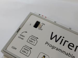
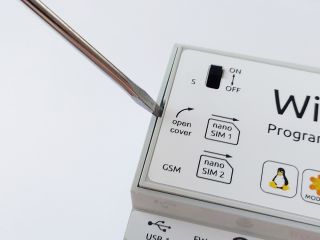
Make sure the '''On/Off''' switch on the front panel is in its aperture. Do not apply excessive force to avoid damaging the switch. | Make sure the '''On/Off''' switch on the front panel is in its aperture. Do not apply excessive force to avoid damaging the switch. | ||
''' | '''Step 3'''. Easily bend the side wall near the connector housing for connecting side modules. With a light insertion, press the pulp into the housing so that the connector enters the opening in the side wall of the housing. | ||
'''Шаг 4'''. Установите заднюю крышку. Защелки крышки должны закрываться с щелчком. | '''Шаг 4'''. Установите заднюю крышку. Защелки крышки должны закрываться с щелчком. | ||
Версия 11:24, 17 августа 2022
Tools
To disassemble the controller, you will need a slotted screwdriver.
Disassembling
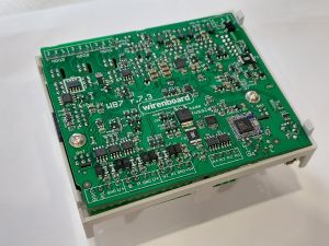
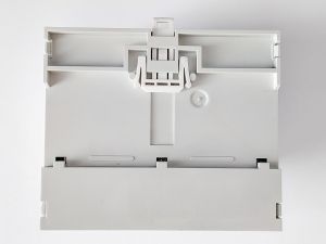
To disassemble the controller, you need to remove the back cover, which is held on by four latches, and extract the circuit board of controller from the case.
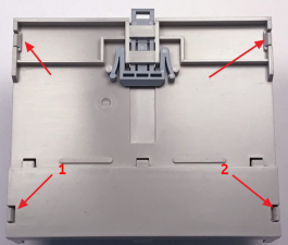
Step 1. Place the controller with the back cover up.
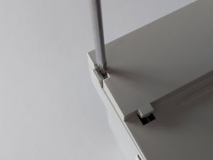
Step 2. Insert a screwdriver between latch №1 and base. With a smooth twisting motion, bend the latch and pull the back cover up. Do the same with latch №2.
Step 3. Use a screwdriver to bend the remaining latches and get the cover.
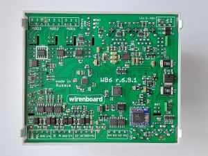
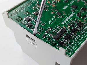
Step 4. Slightly bend the side wall of the case in the place where the connector for connecting external modules is located, and push the controller board out of the case. Do not use too much force to avoid damaging the connector.
Step 1
Step 2
Step 3
Step 4


Assembly
Assembly is carried out in the reverse order.
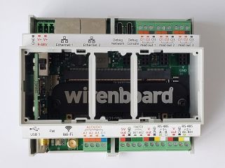
Step 1. Place the controller board in the case.
Step 2. Make sure the On/Off switch on the front panel is in its aperture. Do not apply excessive force to avoid damaging the switch.
Step 3. Easily bend the side wall near the connector housing for connecting side modules. With a light insertion, press the pulp into the housing so that the connector enters the opening in the side wall of the housing.
Шаг 4. Установите заднюю крышку. Защелки крышки должны закрываться с щелчком.
Шаг 1
Шаг 2
Шаг 3
Шаг 4


Снятие крышки
Снимать крышку контроллера требуется для установки сим-карты в GSM-модуль. Крышка держится на четырех защелках, расположенных по сторонам крышки.
Шаг 1. Положите контроллер лицевой стороной вверх.
Шаг 2. Подденьте плоской отверткой защелки крышки контроллера.
Шаг 3. Снимите крышку.
Шаг 1
Шаг 2
Шаг 3


