I/O Mapping Matrix/en: различия между версиями
(Новая страница: «Write in register 5 value 1: <syntaxhighlight lang="bash">modbus_client --debug -mrtu -pnone -s2 /dev/ttyRS485-1 -a1 -t0x06 -r5 1</syntaxhighlight>») |
(Новая страница: «Now all inputs of the module function as inputs for switches with fixation. Disadvantage: Input 0 stops functioning.») |
||
| Строка 152: | Строка 152: | ||
<syntaxhighlight lang="bash">modbus_client --debug -mrtu -pnone -s2 /dev/ttyRS485-1 -a1 -t0x06 -r5 1</syntaxhighlight> | <syntaxhighlight lang="bash">modbus_client --debug -mrtu -pnone -s2 /dev/ttyRS485-1 -a1 -t0x06 -r5 1</syntaxhighlight> | ||
Now all inputs of the module function as inputs for switches with fixation. | |||
Disadvantage: Input 0 stops functioning. | |||
Версия 18:44, 16 июля 2019
Purpose
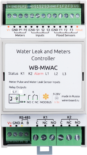
Since v.1.9.0 for devices of WB-MR series and WB-MWAC firmware supports matrix of displaying values of inputs on values of outputs. This additional functionality allows you to flexibly adjust the response of specific outputs of the device depending on the state of its inputs.
Device and operating principle of the mapping matrix
The matrix of actions on outputs for changing input states (mapping matrix) is located in the storage registers of the device, starting from the address 384, and contains 64 registers at the rate of 8 inputs / 8 outputs. Each register contains one of the numeric values that encode the interaction of one of the inputs with one of the outputs.
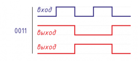
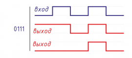
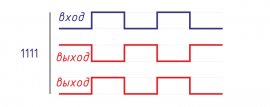
The rows describe the actions when the corresponding input is changed, the columns describe the corresponding outputs. Therefore, the cell at the intersection of the entry date and the exit column contains a value that specifies the operation of the exit when the corresponding entry is changed. The action is described by the value of the lower four bits of the hex word 0b0000 0000 0000 yyxx stored in the register. The yy bits describe the changing of input value from 0 to 1 (front), and the xx bits describe the changing from 1 to 0 (back).
Each combination of two bits describes four possible actions:
- 00 — idle
- 01 — turn off
- 10 — turn on
- 11 — invert value
Thus, it is possible to program the response of each output to the closure and disconnection of any inputs.
Register mapping matrix
| The registers | Outputs | ||||||||
|---|---|---|---|---|---|---|---|---|---|
| 1 | 2 | 3 | 4 | 5 | 6 | 7 | 8 | ||
| Входы | 1 | 384 | 385 | 386 | 387 | 388 | 389 | 390 | 391 |
| 2 | 392 | 393 | 394 | 395 | 396 | 397 | 398 | 399 | |
| 3 | 400 | 401 | 402 | 403 | 404 | 405 | 406 | 407 | |
| 4 | 408 | 409 | 410 | 411 | 412 | 413 | 414 | 415 | |
| 5 | 416 | 417 | 418 | 419 | 420 | 421 | 422 | 423 | |
| 6 | 424 | 425 | 426 | 427 | 428 | 429 | 430 | 431 | |
| 7 | 432 | 433 | 434 | 435 | 436 | 437 | 438 | 439 | |
| 0 | 440 | 441 | 442 | 443 | 444 | 445 | 446 | 447 | |
The previous version of the configuration interaction of the inputs and outputs of relay modules
The new firmware also retained the mechanism for managing input-output links from previous firmware versions. Holding-register 5 describes the behavior of all inputs, and registers 9 to 9+x-1 (x — the number of relays in the module) and register 16 (zero input) — the behavior of each individual input.
Registers can contain the following control values:
| The value of the register | Operation mode inputs | Note |
|---|---|---|
| 0 | Buttons without locking | |
| 1 | latching Switch | |
| 2 | Disable all relays when pressing | with firmware 1.9.0 |
| on| Disable interaction of inputs and outputs | ||
| 4 | Manage according to the Mapping matrix | with firmware v.1.9.0 |
| 5 | Control according to the Mapping matrix, after 20 minutes re-simulate the input state |
with firmware v.1.9.0 |
Setting the control mode of individual inputs is possible only if the value 0 is written in the holding register 5. In the latest firmware in the factory supply, all input mode registers contain 0, except for register 16 — it contains the value 2, which ensures the operation of the input 0 as "emergency" — when you press the button without fixing, connected to this input, all relays will turn off. Pressing it again will leave the relay is off.
Re-simulation of the input state after 20 minutes (mode 5) means that every 20 minutes an action will be performed on the output (according to the matrix), as if the input has just changed the state: if the input is closed, then the action is performed on the rising edge. If open — the on the back. This mode provides additional reliability when controlling the relay leakage sensors connected to the inputs. The following scenario is worked out: when the inlet is closed by the leakage sensor, the ball valve closes the water. At some point, the command to open the crane (for example, Modbus) comes. But, if the leak is still fixed by the sensor, after 20 minutes the tap will be closed again.
= The programming examples of the interaction of inputs and outputs
Let's consider some examples of programming the interaction of inputs and outputs on the example of relay module WB-MR6C with firmware 1.9.4. The module has 7 dry contact inputs and 6 relay outputs. The default input 0 is used to disable all relay modules and the buttons 1 to 6 are used to control relay modules.
In the examples, we focus on the factory settings of the communication parameters of the module, Modbus-address — 1. The module is connected to the first port of the Wiren Board 6 controller.
All examples are executed when the wb-mqtt-serial driver is stopped:
service wb-mqtt-serial stop
Switches with locking
Write in register 5 value 1:
modbus_client --debug -mrtu -pnone -s2 /dev/ttyRS485-1 -a1 -t0x06 -r5 1
Now all inputs of the module function as inputs for switches with fixation. Disadvantage: Input 0 stops functioning.
Чтобы сохранить "аварийный" режим входа 0 вернем в регистр 5 значение 0, а в регистры 9, 10, 11, 12, 13, 14 запишем 1:
modbus_client --debug -mrtu -pnone -s2 /dev/ttyRS485-1 -a1 -t0x06 -r5 0
modbus_client --debug -mrtu -pnone -s2 /dev/ttyRS485-1 -a1 -t0x10 -r9 1 1 1 1 1 1
Теперь все входы функционируют в режиме выключателей с фиксацией, а кратковременное нажатие на кнопку, подключенную ко входу 0, выключит все реле.
Отключить взаимодействие входов и реле
Для отключения взаимодействия входов и реле (например, если мы хотим управлять реле только через движок правил контроллера) запишем в регистр 5 значение 0, а в регистры 9, 10, 11, 12, 13, 14 запишем значение 3:
modbus_client --debug -mrtu -pnone -s2 /dev/ttyRS485-1 -a1 -t0x06 -r5 0
modbus_client --debug -mrtu -pnone -s2 /dev/ttyRS485-1 -a1 -t0x10 -r9 3 3 3 3 3 3
Теперь нажатия на кнопки или переключение выключателей не будет изменять состояние реле: ими можно управлять только программно, по Modbus. При этом функция аварийного входа 0 сохраняется: кратковременное нажатие на кнопку, подключенную ко входу 0, выключит все реле.
Если мы хотим отключить и вход 0, то запишем значение 3 в регистр 16:
modbus_client --debug -mrtu -pnone -s2 /dev/ttyRS485-1 -a1 -t0x06 -r16 3
Использование Mapping-матрицы
Более сложные сценарии взаимодействия входов с реле можно реализовать с помощью Mapping-матрицы. Для использования Mapping-матрицы запишем в holding-регистр 5 значение 0:
modbus_client --debug -mrtu -pnone -s2 /dev/ttyRS485-1 -a1 -t0x06 -r5 4
А в регистры настройки взаимодействия входов/выходов — значение 4:
modbus_client --debug -mrtu -pnone -s2 /dev/ttyRS485-1 -a1 -t0x10 -r 9 4 4 4 4 4 4
modbus_client --debug -mrtu -pnone -s2 /dev/ttyRS485-1 -a1 -t0x06 -r16 4
В заводской поставке Mapping-матрица заполнена нулями. Если вы не уверены в этом и хотите стереть всю матрицу, запишите 0 в каждый из 64 holding-регистров, начиная с 384:
modbus_client --debug -mrtu -pnone -s2 /dev/ttyRS485-1 -a1 -t0x10 -r384 $(printf ' 0%.0s' {1..64})
Вход 0 включает и выключает все реле
Запрограммируем матрицу таким образом, чтобы вход 0, работая в режиме кнопки (выключателя без фиксации) последовательно включал и отключал все реле модуля при замыкании.
Для этого обратимся к карте регистров mapping-матрицы и увидим, что входу 0 соответствуют регистры 440 — 447. Причем за взаимодействие со входами 1 — 6 отвечают регистры 440 — 445.
Мы хотим, чтобы вход работал, как выключатель без фиксации и срабатывал при нажатии (по переднему фронту), а при размыкании ничего бы не происходило. При каждом нажатии состояние всех реле должно инвертироваться. Это соответствует комбинации 11 00: (12, 0x0C) — Изменить состояние выхода при замыкании:

Запишем в регистры 440 — 445 значение 12:
modbus_client --debug -mrtu -pnone -s2 /dev/ttyRS485-1 -a1 -t0x10 -r440 12 12 12 12 12 12
Проверим работу: при первом замыкании входа 0 все реле включаются, при втором — все реле выключаются.
Инвертированный выключатель с фиксацией
Настроим входы таким образом, чтобы при замкнутых входах реле были бы выключены, а при разомкнутых -- включены.
Для этого при замыкании входа (передний фронт) соответствующий выход должен выключаться (01), а при размыкании входа (задний фронт) — включаться (10). Это соответствует значению 6: 
В матрице нужные регистры взаимодействия вход 1 — выход 1, вход 2 — выход 2 и т.д. расположены по диагонали. Это регистры 384, 393, 402, 411, 420, 429. В них надо записать значение 6:
for i in 384 393 402 411 420 429; do modbus_client --debug -mrtu -pnone -s2 /dev/ttyRS485-1 -a1 -t0x06 -r$i 6; done
Обратите внимание: изменение состояния реле происходят только при изменении состояния ввода.
Датчик протечки
Пусть датчик протечки подключен ко входу 1, а реле 1 и 2 управляют приводами шаровых кранов. Реле 3 управляет сигнальной лампой или зуммером. При смачивании датчика протечки реле 1 и реле 2 замыкаются и приводы закрывают шаровые краны. Реле 3 замыкается и включает зуммер. Вход 2 запрограммируем для сброса тревоги и открытия шаровых кранов.
Очистим mapping-матрицу:
modbus_client --debug -mrtu -pnone -s2 /dev/ttyRS485-1 -a1 -t0x10 -r384 $(printf ' 0%.0s' {1..64})
Применим в нашем случае режим, когда состояние входа повторяется каждые 20 минут, для этого запишем в регистр 9 значение 5 (управлять в соответствии с mapping-матрицей, через 20 минут повторно имитировать состояние ввода), а в остальные — значение 4 (управлять в соответствии с mapping-матрицей).
modbus_client --debug -mrtu -pnone -s2 /dev/ttyRS485-1 -a1 -t0x10 -r9 5 4 4 4 4 4
Для входа датчика протечки (вход 1) используем режим 1000 (8) — включать при замыкании. 
Для входа кнопки сброса (вход 2) используем режим 0100 (4) — выключить при замыкании. 
По карте mapping-регистров определяем, что для входа 1 надо записать значение 8 в регистры 384, 385, 386, а для входа 2 — записать значение 4 в регистры 392, 393, 394:
modbus_client --debug -mrtu -pnone -s2 /dev/ttyRS485-1 -a1 -t0x10 -r384 8 8 8
modbus_client --debug -mrtu -pnone -s2 /dev/ttyRS485-1 -a1 -t0x10 -r392 4 4 4
Проверка: замкнем вход 1 и iGND и оставим его замкнутым. Должны включиться реле 1, 2 и 3. Затем замкнем и разомкнем вход 2 — все три реле реле выключились. Ждем 20 минут. Поскольку вход 1 остается замкнутым (протечка не устранена), через 20 минут реле 1, 2 и 3 снова включатся.
Оставляя вход 1 замкнутым, выключим и включим питание реле: через 20 минут реле 1, 2 и 3 снова включатся.


