Modbus/en: различия между версиями
(Новая страница: «=== Modbus request and response data format ===») |
FuzzyBot (обсуждение | вклад) (Часть переводимой страницы Протокол Modbus.) |
||
| (не показано 19 промежуточных версий 3 участников) | |||
| Строка 1: | Строка 1: | ||
<languages/> | <languages/> | ||
=== | === Fundamentals=== | ||
Modbus is a protocol of the applied (seventh) level of the [https://en.wikipedia.org/wiki/OSI_model OSI] model for data exchange, most often between automation devices and is implemented in the form of "request-reply protocol". | |||
Modbus is a | |||
In Wirenboard devices, Modbus data is transmitted over RS-485 serial communication lines. In serial lines RS-485 Protocol is half-duplex and works on the principle of "client-server". Each device on the network (except the master, see below) has an address from 1 to 247, address 0 is used for broadcasting to all devices, and addresses 248-255 are considered reserved according to the Modbus specification, their use is not recommended. | In Wirenboard devices, Modbus data is transmitted over RS-485 serial communication lines. In serial lines RS-485 Protocol is half-duplex and works on the principle of "client-server". Each device on the network (except the master, see below) has an address from 1 to 247, address 0 is used for broadcasting to all devices, and addresses 248-255 are considered reserved according to the Modbus specification, their use is not recommended. | ||
There are two protocol specifications: Modbus RTU and Modbus ASCII. An 11-bit character consisting of 1 start bit, 8 data bits (starting with the lower bit), a parity bit (optional), and 2 stop bits if no parity bit is transmitted, or 1 stop bit if | There are two protocol specifications: Modbus RTU and Modbus ASCII. An 11-bit character consisting of 1 start bit, 8 data bits (starting with the lower bit), a parity bit (optional), and 2 stop bits if no parity bit is transmitted, or 1 stop bit if parity bit is transmitted, is transmitted to the Modbus RTU. This character allows you to transfer 1 byte of data. In Wiren Board devices, the parity bit is not transmitted and 2 stop bits are used. In Modbus ASCII, each byte is transmitted in two characters representing the ASCII codes of the lower and upper four-bit byte groups ([http://www.simplymodbus.ca/ASCII.htm пример]). The Modbus RTU allows you to transmit more information at the same serial line speed and it is used in the Wiren Board devices. All further description applies to Modbus RTU. | ||
| Строка 21: | Строка 20: | ||
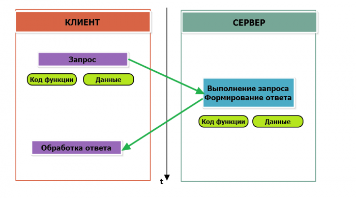
The function is encoded in one byte and determines what action the server device should perform. Function codes range from 1 to 255, with codes 128 to 255 reserved for error messages from the server device. Code 0 is not used. The size of the data block can vary from zero to the maximum allowed. If the request is processed correctly, the server device returns an ADU containing the requested data. | The function is encoded in one byte and determines what action the server device should perform. Function codes range from 1 to 255, with codes 128 to 255 reserved for error messages from the server device. Code 0 is not used. The size of the data block can vary from zero to the maximum allowed. If the request is processed correctly, the server device returns an ADU containing the requested data. | ||
[[ | [[File:Modbus_transaction_OK.png|700px|thumb|center|Modbus-transaction without errors]] | ||
---- | ---- | ||
| Строка 63: | Строка 62: | ||
Holding Registers and Input Registers are represented by a two-byte word and can store values from 0 to 65535 (0x0000 — 0xFFFFF). | Holding Registers and Input Registers are represented by a two-byte word and can store values from 0 to 65535 (0x0000 — 0xFFFFF). | ||
Input registers are read-only (e.g. current temperature). Storage registers support both read and write (to store settings). Currently, in many devices, particularly Wiren Board devices, these registers are not separated. Commands to read the storage register N and the input register N will access the same value in the address space of the device. | Input registers are read-only (e.g. current temperature). Storage registers support both read and write (to store settings). Currently, in many devices, particularly Wiren Board devices, these registers are not separated. Commands to read the storage register N and the input register N will access the same value in the address space of the device. | ||
===Registers addresses and numbers=== | ===Registers addresses and numbers=== | ||
| Строка 115: | Строка 113: | ||
[[File:SDM220_Template.png|700px|thumb|center|Template Fragment for SDM220 meter]] | [[File:SDM220_Template.png|700px|thumb|center|Template Fragment for SDM220 meter]] | ||
=== Register reading and writing function codes === | === Register reading and writing function codes === | ||
| Строка 155: | Строка 152: | ||
=== Modbus request and response data format === | === Modbus request and response data format === | ||
Let's take a closer look at how data is exchanged between the client device sending the request and the server device responding to it. The following figure shows how the controller communicates with a device with address 0x01. We want to read 8 coil registers starting from the first one. | |||
[[ | [[File:Read_8_Coils_2.png|600px|thumb|center|Data exchange in Modbus]] | ||
We have received a hexadecimal number 0x2D as data, so the state of eight coil registers in binary form is: 0b10110100. | |||
---- | ---- | ||
The following table shows the query and response data structures for the main Modbus functions. | |||
{|class="wikitable" align="center" | {|class="wikitable" align="center" | ||
! | !Function code || Request || Reply | ||
|- | |- | ||
! 1 (Read Coils) и 2 (Read Discrete Inputs) | ! 1 (Read Coils) и 2 (Read Discrete Inputs) | ||
|<ul><li> | |<ul><li>Address of the first flag register or input register (16 бит)</li><li>Amount of data (8 values per byte)</li><ul>|| <ul><li>The number of transmitted bytes (8 bits)</li><li>Flag register or input register values (8 values per byte)</li></ul> | ||
|- | |- | ||
! 3 (Read Holding Registers) и 4 (Read Input Registers) | ! 3 (Read Holding Registers) и 4 (Read Input Registers) | ||
|<ul><li> | |<ul><li>The address of the first register (16 bit)</li><li>Number of registers to read</li><ul>|| <ul><li>The number of transmitted bytes (8 bits)</li><li>The values of the registers (16 bit 1 register)</li></ul> | ||
|- | |- | ||
! 5 (Write Single Coil) | ! 5 (Write Single Coil) | ||
|<ul><li> | |<ul><li>Register address (16 bit)</li><li>The value to be written (0 — off, 0xFF00 — on)</li><ul>|| The answer is similar to the request | ||
|- | |- | ||
! 6 (WriteSingle Register) | ! 6 (WriteSingle Register) | ||
|<ul><li>Адрес регистра(16 бит)</li><li> | |<ul><li>Адрес регистра(16 бит)</li><li>The new value of the register (16-bit)</li></ul>|| The answer is similar to the request | ||
|- | |- | ||
! 15 (WriteMultipleCoils) | ! 15 (WriteMultipleCoils) | ||
| <ul><li> | | <ul><li>Address of the first flag register to write (16 bit)</li><li>Number of flag registers to write (16 bits)</li><li>Number of bytes of data transmitted for flag registers (8 bits)</li><li>Data (8 registers the flags in bytes)</li></ul> || <ul><li>Address of the first coil register (16 bit)</li><li>The recorded number of coil registers(16-bit)</li></ul> | ||
|- | |- | ||
! 16 (Write Multiple register ) | ! 16 (Write Multiple register ) | ||
| <ul><li> | | <ul><li>The address of the first storage register for recording (16-bits)</li><li>Number of holding registers to write (16 bits)</li><li>the Number of transmitted data bytes for the registers (8-bit)</li><li>Data (16 bytes per register)</li></ul> || <ul><li>The address of the first storage register (16 bits)</li><li>Number of written holding registers(16 bit)</li></ul> | ||
|- | |- | ||
|} | |} | ||
=== | === Modbus Exception codes (errors) === | ||
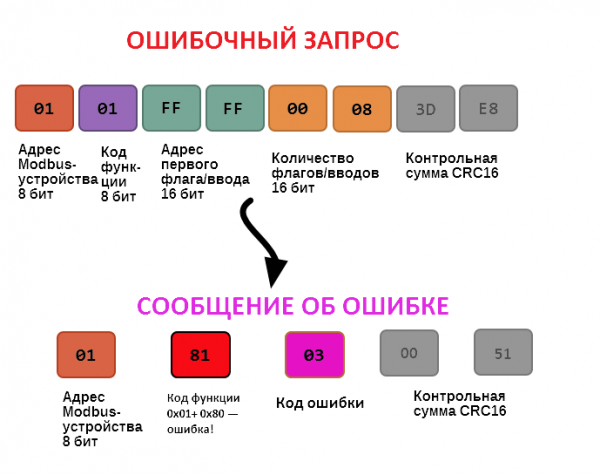
If the request cannot be processed by the server device for one reason or another, it sends an error message in response. The error message contains the address of the Modbus device, the code of the function in which the error occurred, increased by 0x80, the error code and the checksum: | |||
[[ | [[File:Read_8_Coils_ERR.png|600px|thumb|center|Transaction failed]] | ||
In this case, we tried to access the nonexistent register address 0xFFFF and tried to read 8 flag registers. As a result, we received error code 0x03 — "an invalid value was passed in The data field". | |||
The most common Modbus error codes are listed in the following table: | |||
{|class="wikitable" align="center" | {|class="wikitable" align="center" | ||
! | !Error Code || Error name|| Meaning | ||
|- | |- | ||
! 1 | ! 1 | ||
| Illegal Function || | | Illegal Function || An invalid function code was sent in the request | ||
|- | |- | ||
! 2 | ! 2 | ||
| Illegal Data Address || | | Illegal Data Address ||Illegal Data Address | ||
|- | |- | ||
! 3 | ! 3 | ||
| Illegal Data Value || | | Illegal Data Value || Illegal Data Value | ||
|- | |- | ||
! 4 | ! 4 | ||
| Slave Device Failure || | | Slave Device Failure ||An unrecoverable error occurred on the device while performing the requested operation | ||
|- | |- | ||
! 5 | ! 5 | ||
| Acknowledge || | | Acknowledge ||Request is accepted, executed, but will take a long time to complete; you must increase the timeout. | ||
|- | |- | ||
! 6 | ! 6 | ||
| Slave Device Busy || | | Slave Device Busy || The device is busy processing the previous request. | ||
|- | |- | ||
! 7 | ! 7 | ||
| Negative Acknowledge || | | Negative Acknowledge || The device cannot fulfill the request, you must obtain additional diagnostic information from the device. Maintenance may be required. | ||
|- | |- | ||
! 8 | ! 8 | ||
| Memory Parity Error || | | Memory Parity Error || Parity Error when accessing the internal memory of the device. | ||
|- | |- | ||
|} | |} | ||
| Строка 229: | Строка 226: | ||
=== | === Modbus checksum calculation === | ||
For the Modbus RTU Protocol, the 16-bit checksum (CRC) is calculated using the algorithm described in the [http://www.modbus.org/specs.php Modbus] specification in ''the Modbus Serial Line Protocol and Implementation Guide, CRC-generation section''. The sending device generates two bytes of checksum based on the message data, and the receiving device recalculates the checksum and compares it with the received one. The coincidence of the accepted and calculated modbud RTU checksum is considered an indicator of successful data exchange. | |||
In the case of limited computing resources for the calculation of the checksum, there is a function that uses table values (also given in the specification). | |||
Текущая версия на 16:34, 7 июля 2021
Fundamentals
Modbus is a protocol of the applied (seventh) level of the OSI model for data exchange, most often between automation devices and is implemented in the form of "request-reply protocol".
In Wirenboard devices, Modbus data is transmitted over RS-485 serial communication lines. In serial lines RS-485 Protocol is half-duplex and works on the principle of "client-server". Each device on the network (except the master, see below) has an address from 1 to 247, address 0 is used for broadcasting to all devices, and addresses 248-255 are considered reserved according to the Modbus specification, their use is not recommended.
There are two protocol specifications: Modbus RTU and Modbus ASCII. An 11-bit character consisting of 1 start bit, 8 data bits (starting with the lower bit), a parity bit (optional), and 2 stop bits if no parity bit is transmitted, or 1 stop bit if parity bit is transmitted, is transmitted to the Modbus RTU. This character allows you to transfer 1 byte of data. In Wiren Board devices, the parity bit is not transmitted and 2 stop bits are used. In Modbus ASCII, each byte is transmitted in two characters representing the ASCII codes of the lower and upper four-bit byte groups (пример). The Modbus RTU allows you to transmit more information at the same serial line speed and it is used in the Wiren Board devices. All further description applies to Modbus RTU.
The master device periodically polls the slave or server. The master has no address, the transmission of messages from the device server to the host without asking the host in the protocol is not provided.
The Modbus data package looks as shown in the figure. A PDU (Protocol Data Unit) is a common part of a MODBUS package that includes the function code and data of the package. ADU (Application Data Unit) is a complete Modbus package. Includes a physical layer-specific part of the package and PDU. For serial lines, the device address is passed in the ADU header, and the CRC16 checksum is passed at the end. The maximum ADU size in serial communication lines is 253 bytes (1 byte of the address and two bytes of the checksum are subtracted from the maximum 256 bytes allowed by the specification). For reference — in Modbus TCP, the maximum packet length is 260 bytes.
The function is encoded in one byte and determines what action the server device should perform. Function codes range from 1 to 255, with codes 128 to 255 reserved for error messages from the server device. Code 0 is not used. The size of the data block can vary from zero to the maximum allowed. If the request is processed correctly, the server device returns an ADU containing the requested data.
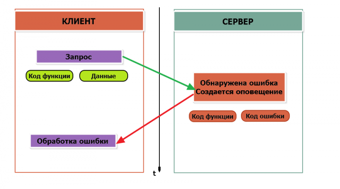
If an error occurs, the device returns an error code. In the case of a normal transaction, the function code in the response is returned unchanged; in the case of an error, the highest bit of the function code is set to one (that is, the function code + 0x80)
It is necessary to determine the timeout waiting for a response from the slave — it is pointless to wait a long time for an answer, which, perhaps, due to some error will never come.
Modbus data structures
In Modbus it is customary to encode addresses and data in the big-endian format, when bytes are starting with the high: for example, when transmitting the hexadecimal number 0x1234, the device will first accept the byte 0x12, and then — 0x34. To transfer data of another type, for example, float numbers, text strings, date and time of day, etc. the manufacturer can choose its own method of encoding — for data decrypting it is important to get acquainted with the specification of the device manufacturer.
Modbus data model
Data exchange with Modbus devices takes place via registers. The Modbus Protocol defines four types of registers shown in the table:
| Table | Size | Access |
|---|---|---|
| Coils | 1 bit | read and write |
| Discrete Inputs | 1 bit | read only |
| Holding Registers | 16-bit word | read and write |
| Input Registers | 16-bit word | read only |
Coils store single-bit values - they can be in the 0 or 1 state. These registers can indicate the current state of the output (whether the relay is off or on). The name "coil" literally means the winding-actuator of an electromechanical relay. Flag registers allow both reading and writing.
Discrete inputs are also single-bit registers that describe the state of the device input (for example, voltage — 1). These registers are read-only.
Holding Registers and Input Registers are represented by a two-byte word and can store values from 0 to 65535 (0x0000 — 0xFFFFF). Input registers are read-only (e.g. current temperature). Storage registers support both read and write (to store settings). Currently, in many devices, particularly Wiren Board devices, these registers are not separated. Commands to read the storage register N and the input register N will access the same value in the address space of the device.
Registers addresses and numbers
In the Modbus standard for each of the four types of registers are used in different tables with the numbers 0,1,3,4. Thus, a register of a certain type with a certain number (otherwise it is called a physical address) has its own address in the corresponding table.
| Table | Table number | Initial logical address | Register number (physical address) | Logical address range |
|---|---|---|---|---|
| Coils | 0 | 000001 | 0 | 000001 — 065535 |
| Discrete Inputs | 1 | 100001 | 0 | 100001 — 165535 |
| Holding Registers | 3 | 300001 | 0 | 300001 — 365535 |
| Input Registers | 4 | 400001 | 0 | 400001 — 465535 |
This misleads how to access the register with the desired number. Moreover, the terms "address" and "register" can be used by the manufacturer arbitrarily. Most often register numbers are specified, such as for Wiren Board devices.In some devices a shorter logical address is applied (.0001 — .9999), and the address uses 5, not 6 digits.
Sometimes the description of a device shall contain only logical addresses. For example, coil register 0 has the address 000001, input register 4 — 400005, etc.
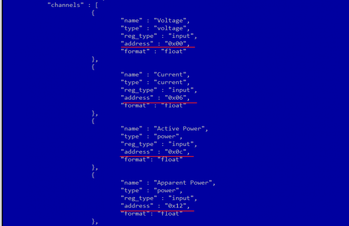
The ready-made device templates of the Wiren Board 5 controller have a template for a single-phase electricity meter SDM220 (/usr/share/wb-mqtt-serial/templates/config-sdm220.json). In the documentation "Eastron SDM 220 Modbus Smart Meter Modbus Protocol Implementation V1.0" from the manufacturer the registers and the corresponding measured parameters are listed, for example:
| Address (Register) | Description | Units | Modbus Protocol Start Address Hex (Hi Byte Lo Byte) |
|---|---|---|---|
| 30001 | Line to neutral volts. | Volts | 00 00 |
| 30007 | Current. | Amps. | 00 06 |
| 30013 | Active power | Whatts | 00 0C |
| 30019 | Apparent power | VoltAmps | 00 12 |
| ... | ... | ... | ... ... |
The manufacturer provides both logical and physical addresses of the registers in the table, which allows us to easily create a device template and illustrate the connection between the logical and physical addresses of the Modbus registers.
Register reading and writing function codes
The following table shows the most common Modbus function codes:
| Function code | HEX | Name |
|---|---|---|
| 1 | 0x01 | Read Coils |
| 2 | 0x02 | Read Discrete Inputs |
| 3 | 0x03 | Read Holding Registers |
| 4 | 0x04 | Read Input Registers |
| 5 | 0x05 | Write Single Coil |
| 6 | 0x06 | Write Single Register |
| 15 | 0x0F | Write Multiple Coils |
| 16 | 0x10 | Write Multiple Register |
Commands can be divided by types: reading values of record values; operation with a single — value operation on multiple values.
Modbus request and response data format
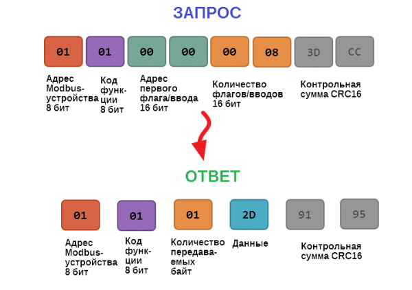
Let's take a closer look at how data is exchanged between the client device sending the request and the server device responding to it. The following figure shows how the controller communicates with a device with address 0x01. We want to read 8 coil registers starting from the first one.
We have received a hexadecimal number 0x2D as data, so the state of eight coil registers in binary form is: 0b10110100.
The following table shows the query and response data structures for the main Modbus functions.
| Function code | Request | Reply |
|---|---|---|
| 1 (Read Coils) и 2 (Read Discrete Inputs) |
|
|
| 3 (Read Holding Registers) и 4 (Read Input Registers) |
|
|
| 5 (Write Single Coil) |
|
The answer is similar to the request |
| 6 (WriteSingle Register) |
|
The answer is similar to the request |
| 15 (WriteMultipleCoils) |
|
|
| 16 (Write Multiple register ) |
|
|
Modbus Exception codes (errors)
If the request cannot be processed by the server device for one reason or another, it sends an error message in response. The error message contains the address of the Modbus device, the code of the function in which the error occurred, increased by 0x80, the error code and the checksum:
In this case, we tried to access the nonexistent register address 0xFFFF and tried to read 8 flag registers. As a result, we received error code 0x03 — "an invalid value was passed in The data field".
The most common Modbus error codes are listed in the following table:
| Error Code | Error name | Meaning |
|---|---|---|
| 1 | Illegal Function | An invalid function code was sent in the request |
| 2 | Illegal Data Address | Illegal Data Address |
| 3 | Illegal Data Value | Illegal Data Value |
| 4 | Slave Device Failure | An unrecoverable error occurred on the device while performing the requested operation |
| 5 | Acknowledge | Request is accepted, executed, but will take a long time to complete; you must increase the timeout. |
| 6 | Slave Device Busy | The device is busy processing the previous request. |
| 7 | Negative Acknowledge | The device cannot fulfill the request, you must obtain additional diagnostic information from the device. Maintenance may be required. |
| 8 | Memory Parity Error | Parity Error when accessing the internal memory of the device. |
Modbus checksum calculation
For the Modbus RTU Protocol, the 16-bit checksum (CRC) is calculated using the algorithm described in the Modbus specification in the Modbus Serial Line Protocol and Implementation Guide, CRC-generation section. The sending device generates two bytes of checksum based on the message data, and the receiving device recalculates the checksum and compares it with the received one. The coincidence of the accepted and calculated modbud RTU checksum is considered an indicator of successful data exchange.
In the case of limited computing resources for the calculation of the checksum, there is a function that uses table values (also given in the specification).

