RS-485: Wiring and Connection/en: различия между версиями
(Новая страница: «RS-485:Physical connection») |
FuzzyBot (обсуждение | вклад) м (FuzzyBot переименовал страницу RS-485:Физическое подключение/en в RS-485: Wiring and Connection/en без оставления перенаправления: Часть переводимой страницы RS-485:Физическое подключение.) |
||
| (не показано 20 промежуточных версий 1 участника) | |||
| Строка 1: | Строка 1: | ||
<languages/> | <languages/> | ||
'''[https://wirenboard.com/ru/product/cable-KSPEVG/ | '''[https://wirenboard.com/ru/product/cable-KSPEVG/ Buy cable in the online store]''' | ||
For General information on connecting RS-485 devices to the controller, see page [[RS-485/en|RS-485]]. | |||
== | == Busbar laying == | ||
All RS-485 devices are installed on the same bus. The bus uses two data lines (''A'' and ''B''), and it is also often convenient to lay two power lines - ''GND'' and ''+12V'' (or other supply voltage). | |||
''' | '''Wire A is connected to terminal a on all devices, wire B is always connected to B.''' | ||
It is necessary to use a pair twist cable: the RS-485 data (lines A and B) must form a twisted pair. If the same cable is used to power the devices, it is necessary to pay attention to the cross section of the conductors: a voltage drop on a long line can lead to the fact that the devices will not work. Finally, you should choose a shielded cable. | |||
When installing, it is convenient to use a cable with flexible conductors. Examples are given below: | |||
{| class="wikitable" | {| class="wikitable" | ||
! | !Name | ||
! | !Flexible | ||
! | !Section of the conductor | ||
! | !Twisted pair | ||
! | !Screen | ||
! | !Approximate price, $/m | ||
|- | |- | ||
|[https://paritet.su/catalog/gibkie_kspvg_kspevg/kspevg_2kh2kh0_35_mm_kv/ | |[https://paritet.su/catalog/gibkie_kspvg_kspevg/kspevg_2kh2kh0_35_mm_kv/ XPMG 2x2x0.35] | ||
| | |yes | ||
|0.35 | |0.35 | ||
| | |yes | ||
| | |aluminium polyethylene tape | ||
|0.4 | |0.4 | ||
|- | |- | ||
|[http://www.paritet-podolsk.ru/produkciya/signal/liycy_tp/ | |[http://www.paritet-podolsk.ru/produkciya/signal/liycy_tp/ LiYCY TP 2х2х0,50] | ||
| | |yes | ||
|0.5 | |0.5 | ||
| | |yes | ||
| | |braid | ||
|1 | |1 | ||
|- | |- | ||
|[http://www.paritet-podolsk.ru/produkciya/signal/liycy_tp/ | |[http://www.paritet-podolsk.ru/produkciya/signal/liycy_tp/ LiYCY TP 2х2х0,35] | ||
| | |yes | ||
|0.35 | |0.35 | ||
| | |yes | ||
| | |braid | ||
|0.8 | |0.8 | ||
|- | |- | ||
|[https://paritet.su/catalog/kis_v/kis_v_2kh2kh0_60/ | |[https://paritet.su/catalog/kis_v/kis_v_2kh2kh0_60/ KIS-V 2х2х0,60] | ||
| | |yes | ||
|0.6 | |0.6 | ||
| | |yes | ||
| | |braid | ||
|1.1 | |1.1 | ||
|} | |} | ||
Also, for bus laying, you can use a conventional twisted pair CAT5 for Ethernet - for it below is a standard wiring diagram (the usual wave resistance of such cable is 100 Ohms). | |||
{| class="wikitable" | {| class="wikitable" | ||
|+ | |+ Use of category 5 network cable for RS-485 bus laying | ||
! | !Bus signal RS-485!!Wire | ||
|- | |- | ||
| | |Data A | ||
|[[File:Wire white green stripe.svg|60px|Pair 3 Wire 1]] | |[[File:Wire white green stripe.svg|60px|Pair 3 Wire 1]] white-green | ||
|- | |- | ||
| | |Data B | ||
|[[File:Wire green.svg|60px|Pair 3 Wire 2]] | |[[File:Wire green.svg|60px|Pair 3 Wire 2]] green | ||
|- | |- | ||
| | |power supply (12V or other) | ||
|[[File:Wire orange.svg|60px|Pair 2 Wire 2]] | |[[File:Wire orange.svg|60px|Pair 2 Wire 2]] orange | ||
|- | |- | ||
| | |power supply (12V or other) | ||
|[[File:Wire white orange stripe.svg|60px|Pair 2 Wire 1]] | |[[File:Wire white orange stripe.svg|60px|Pair 2 Wire 1]] white-orange | ||
|- | |- | ||
| | |not used | ||
|[[File:Wire blue.svg|60px|Pair 1 Wire 2]] | |[[File:Wire blue.svg|60px|Pair 1 Wire 2]] blue | ||
|- | |- | ||
| | |not used | ||
|[[File:Wire white blue stripe.svg|60px|Pair 1 Wire 1]] | |[[File:Wire white blue stripe.svg|60px|Pair 1 Wire 1]] white-blue | ||
|- | |- | ||
| | |ground power supply(GND) | ||
|[[File:Wire white brown stripe.svg|60px|Pair 4 Wire 1]] | |[[File:Wire white brown stripe.svg|60px|Pair 4 Wire 1]] white-brown | ||
|- | |- | ||
| | |ground power supply (GND) | ||
|[[File:Wire brown.svg|60px|Pair 4 Wire 2]] | |[[File:Wire brown.svg|60px|Pair 4 Wire 2]] brown | ||
|} | |} | ||
{{warning|1=При подключении внешних устройств к Wiren Board по шине RS-485, нужно соединять не только линии передачи данных A и B, но и '''земли''' (общий провод) контроллера Wiren Board и внешних устройств. Подключение общего провода необходимо в случае подключения к неизолированному порту RS-485 и рекомендуется в случае подключения к гальванически изолированному порту.}} | {{warning|1=При подключении внешних устройств к Wiren Board по шине RS-485, нужно соединять не только линии передачи данных A и B, но и '''земли''' (общий провод) контроллера Wiren Board и внешних устройств. Подключение общего провода необходимо в случае подключения к неизолированному порту RS-485 и рекомендуется в случае подключения к гальванически изолированному порту.}} | ||
{{warning|1= When connecting external devices to the Wiren Board via the RS-485 bus, it is necessary to connect not only the data lines A and B, but also the ground (common wire) of the Wiren Board controller and external devices. The connection of a common wire is required when connected to an uninsulated RS-485 port and is recommended when connected to a galvanically isolated port.}} | |||
The common wire terminal is designated, according to the equipment, as SC, SG, G, GND, ground or reference. On the Wiren Board controllers, this terminal is designated as GND. When connecting to an isolated port, you need to connect to the isolated ground of the port ("GND iso"terminals). | |||
If your bus is longer than 100 meters, it is desirable to install a terminal resistor at its end (about 150 Ohms, see more in [https://ru.wikipedia.org/wiki/RS-485#.D0.A1.D0.BE.D0.B3.D0.BB.D0.B0.D1.81.D0.BE.D0.B2.D0.B0.D0.BD.D0.B8.D0.B5 Wikipedia]). For long lines, there are also recommendations to terminate unused cable conductors at both ends. | |||
== | == Connecting devices == | ||
{|align="right" | {|align="right" | ||
|-valign="top" | |-valign="top" | ||
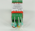
|[[Файл:M1W2PODKL.png|thumb|150px| | |[[Файл:M1W2PODKL.png|thumb|150px|Tips for RS-485 bus]] | ||
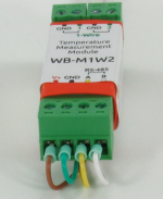
|[[Файл:M1W2PODKL2.png|thumb|150px| | |[[Файл:M1W2PODKL2.png|thumb|150px|Connecting the RS-485 bus to the WB-M1W2 bus coupler]] | ||
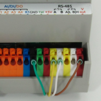
|[[Файл:WBPODKL.png|thumb|200px| | |[[Файл:WBPODKL.png|thumb|200px|Connecting the RS-485 to Wiren Board 5]] | ||
|} | |} | ||
Since all devices are connected by a common bus, make sure the quality of the connection of all nodes of the line: | |||
* | *when the line is broken, the devices behind the break will not operate | ||
* | *when the line is broken, the devices behind the break will not operate | ||
We recommend the use of whip tips for a swage [http://www.chipdip.ru/catalog-show/tips/ pin tips for crimping]. This makes it easy to connect and disconnect devices without losing the operation of other devices on the bus. When used with the mounting lugs of the NSVI it is necessary that the diameter of the insulated cuff does not exceed the dimensions of the terminals of the devices. | |||
Wire A on all devices is connected to the terminal strip marked A, wire B - always to B. On the wire Board next to the terminals A and B are GND and Vout terminals - you can immediately connect the power lines (first check the power requirements of your devices!). | |||
Life hack: since there are stretching lines inside the Wiren Board controller, after connecting it to the bus line A voltage will be greater than b by about 0.5 V. Therefore, connecting peripherals you can easily determine the bus line by the voltmeter. But, of course, color coding of conductors is more preferable. | |||
== | == Additional information == | ||
# | #The differential line gives good noise immunity. The length of the line is up to 1200 meters. | ||
# | #When laying the bus, you need to follow [http://www.gaw.ru/html.cgi/txt/interface/rs485/app.htm certain rules], but for transmission in one apartment, any cable will fit and even branches are possible. | ||
Текущая версия на 12:09, 17 июня 2022
For General information on connecting RS-485 devices to the controller, see page RS-485.
Busbar laying
All RS-485 devices are installed on the same bus. The bus uses two data lines (A and B), and it is also often convenient to lay two power lines - GND and +12V (or other supply voltage).
Wire A is connected to terminal a on all devices, wire B is always connected to B.
It is necessary to use a pair twist cable: the RS-485 data (lines A and B) must form a twisted pair. If the same cable is used to power the devices, it is necessary to pay attention to the cross section of the conductors: a voltage drop on a long line can lead to the fact that the devices will not work. Finally, you should choose a shielded cable.
When installing, it is convenient to use a cable with flexible conductors. Examples are given below:
| Name | Flexible | Section of the conductor | Twisted pair | Screen | Approximate price, $/m |
|---|---|---|---|---|---|
| XPMG 2x2x0.35 | yes | 0.35 | yes | aluminium polyethylene tape | 0.4 |
| LiYCY TP 2х2х0,50 | yes | 0.5 | yes | braid | 1 |
| LiYCY TP 2х2х0,35 | yes | 0.35 | yes | braid | 0.8 |
| KIS-V 2х2х0,60 | yes | 0.6 | yes | braid | 1.1 |
Also, for bus laying, you can use a conventional twisted pair CAT5 for Ethernet - for it below is a standard wiring diagram (the usual wave resistance of such cable is 100 Ohms).
{{#invoke:Template translation|renderTranslatedTemplate|template=Template:Warning|noshift=1}}
{{#invoke:Template translation|renderTranslatedTemplate|template=Template:Warning|noshift=1}} The common wire terminal is designated, according to the equipment, as SC, SG, G, GND, ground or reference. On the Wiren Board controllers, this terminal is designated as GND. When connecting to an isolated port, you need to connect to the isolated ground of the port ("GND iso"terminals).
If your bus is longer than 100 meters, it is desirable to install a terminal resistor at its end (about 150 Ohms, see more in Wikipedia). For long lines, there are also recommendations to terminate unused cable conductors at both ends.
Connecting devices
Since all devices are connected by a common bus, make sure the quality of the connection of all nodes of the line:
- when the line is broken, the devices behind the break will not operate
- when the line is broken, the devices behind the break will not operate
We recommend the use of whip tips for a swage pin tips for crimping. This makes it easy to connect and disconnect devices without losing the operation of other devices on the bus. When used with the mounting lugs of the NSVI it is necessary that the diameter of the insulated cuff does not exceed the dimensions of the terminals of the devices.
Wire A on all devices is connected to the terminal strip marked A, wire B - always to B. On the wire Board next to the terminals A and B are GND and Vout terminals - you can immediately connect the power lines (first check the power requirements of your devices!).
Life hack: since there are stretching lines inside the Wiren Board controller, after connecting it to the bus line A voltage will be greater than b by about 0.5 V. Therefore, connecting peripherals you can easily determine the bus line by the voltmeter. But, of course, color coding of conductors is more preferable.
Additional information
- The differential line gives good noise immunity. The length of the line is up to 1200 meters.
- When laying the bus, you need to follow certain rules, but for transmission in one apartment, any cable will fit and even branches are possible.


