Using Wiren Board with peripheral devices/en: различия между версиями
Fizikdaos (обсуждение | вклад) (Новая страница: «These devices form a signal by closing suitable for them two wires.») |
FuzzyBot (обсуждение | вклад) м (FuzzyBot переименовал страницу Connecting peripheral devices/en в Using Wiren Board with peripheral devices/en без оставления перенаправления: Часть переводимой страницы Connecting peripheral devices.) |
||
| (не показана 41 промежуточная версия 3 участников) | |||
| Строка 19: | Строка 19: | ||
For overvoltage protection controller integrated protective diodes - external protective elements are not required. | For overvoltage protection controller integrated protective diodes - external protective elements are not required. | ||
Also for low-voltage load switching, you can use digital output module (WBIO-DO-HS-8), see. [[Special: MyLanguage / | Also for low-voltage load switching, you can use digital output module (WBIO-DO-HS-8), see. [[Special:MyLanguage/Модули ввода-вывода| Modules IO]]. | ||
| Строка 43: | Строка 43: | ||
Also for the connection of current sensors designed special [[Wiren Board 5: Модуль расширения ADC | extension module]]. | Also for the connection of current sensors designed special [[Special:MyLanguage/Wiren Board 5: Модуль расширения ADC | extension module]]. | ||
| Строка 56: | Строка 56: | ||
For a more accurate measurement of resistance, as well as to connect Pt100, Pt1000 and for two- and three-wire circuit | For a more accurate measurement of resistance, as well as to connect Pt100, Pt1000 and for two- and three-wire circuit | ||
is a special [[Wiren Board 5: | is a special [[Special:MyLanguage/Wiren Board 5: Модуль расширения ADC| extension module]]. | ||
| Строка 64: | Строка 64: | ||
[[File:Button.png|thumb|400px|Example of connection a button]] | [[File:Button.png|thumb|400px|Example of connection a button]] | ||
These devices form a signal by closing | These devices form a signal by closing two wires. | ||
Connection Methods to the controller: | |||
* | * With Ax terminal controller. Connect one wire to the power supply 5-24V, the second wire to the terminal Ax. | ||
* | * Using input-output module WBIO-DI-DR-8 (8 channels), see. [[Special: MyLanguage/Модули ввода-вывода | IO Modules ]]. One of the wires connected to GND, the second to terminal Dx of module. | ||
* | * Using extension module [[Special: MyLanguage/WBE-DI-DR-3|WBE-DI-DR-3]] (3 channels). One of the wires connected to GND, the second terminal of the Ox in the corresponding expansion module. | ||
* | * Can be connected to the inputs Rx controller, including internal current source. One of the wires connected to GND, the second to the Rx controller. | ||
Some counters have a pulse output to optocoupler, then two wires have the correct polarity - "plus" and "minus". | |||
In this case, minus connected to GND, and the "plus" to the input. | |||
Or "plus" to the power supply, negative to Ax (first method). | |||
== | == Devices with open collector output == | ||
| Строка 88: | Строка 88: | ||
And a controller '' 'to have a common ground' ''. | |||
There are several methods to connect these devices to the controller: | |||
* | * Using input-output module WBIO-DI-DR-8 (8 channels), see. [[Special: MyLanguage/Модули ввода-вывода|IO Modules ]]. The output "open collector" connect to terminal Dx module. | ||
* | * Using extension module [[Special: MyLanguage/WBE-DI-DR-3 |WBE-DI-DR-3]] (3 channels). The output "open collector" connect to terminal Ox corresponding extension module. | ||
* | * It can be connected to Rx inputs controller, activating the inside current. | ||
== | == Contactors with a 110/250V control voltage == | ||
Use the extension module with relay outputs, eg[[Special:MyLanguage/Модули ввода-вывода#Модуль релейных выходов (WBIO-DO-R3A-8)|WBIO-DO-R3A-8]]. | |||
Connect the control contactor coil through the relay extension module (see. Figure). | |||
Expansion module contains TVS, protect the relay contacts from arcing. Exterior protective components is not required. | |||
== | == Connecting to the 1-Wire network == | ||
Ground connect to GND or common ground bus. | |||
The data line to 1-Wire terminal. | |||
The supply line to 5Vout terminal (internal power supply). | |||
It is allowed to use external power supply bus 1-Wire. | |||
When using a passive power supply pin of each sensor is connected to the earth wire. | |||
In this case, the bus consists two wires attached, respectively, to '1-Wire "and" GND ". | |||
== | == Connecting to RS-485 network == | ||
See [[Special:MyLanguage/RS-485|RS-485]]. | |||
Wiren Board 5 has two RS-485 port. The second port is multiplexed with the port CAN (L with A, H with B) | |||
Line A B is connected to terminals A and B respectively. Signal ground (if any) connected to the ground controller. | |||
If the RS-485 network is long enough, then it is recommended to use [[Wiren Board 5: Модуль расширения RS485-ISO|extension module with galvanically-isolated RS-485]]. | |||
| Строка 147: | Строка 147: | ||
=== | === Example of connection devices === | ||
Schematic test stand - [[Файл:Стенд-hi.jpg|thumb|500px|Schematic test stand]] | |||
Текущая версия на 20:08, 20 мая 2021
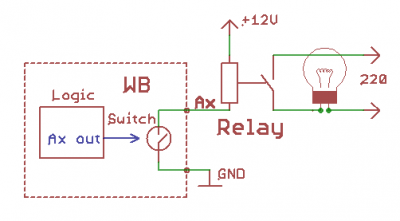
Switching low-voltage load
Examples: 12/24V relay , LED, fans, signal lamps and so on.
Connect '+' load to "+" power supply, and "-" to terminal Ax.
If the total current per channel over 2 A connect GND terminal to the "-" power supply.
When switching inductive loads (relay), there are voltage spikes.
For overvoltage protection controller integrated protective diodes - external protective elements are not required.
Also for low-voltage load switching, you can use digital output module (WBIO-DO-HS-8), see. Modules IO.
Sensors with analog voltage output
Example: temperature sensors.
Connect the device to a terminal GND or to a common ground. The sensor output is connected to one of the terminals Ax or Rx. Channels Ax / Rx have different ranges of the measured voltages. Choose the the best channel for your sensor.
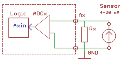
Sensors with analog current output
Special current inputs in the WB absent but it is possible, using a resistor Rx = 100-300Om, the current is converted into a voltage and connect as in the previous.
Also for the connection of current sensors designed special extension module.
Resistive Sensors
Inputs Rx are designed to measure resistance in the range 1-100kOm. Measured resistance is connected between the GND and Rx.
For a more accurate measurement of resistance, as well as to connect Pt100, Pt1000 and for two- and three-wire circuit
is a special extension module.
Sensors / meters with pulse output / button
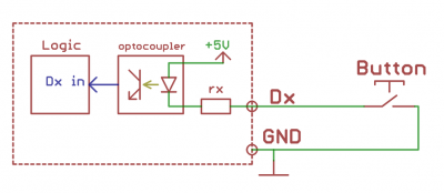
These devices form a signal by closing two wires.
Connection Methods to the controller:
- With Ax terminal controller. Connect one wire to the power supply 5-24V, the second wire to the terminal Ax.
- Using input-output module WBIO-DI-DR-8 (8 channels), see. IO Modules . One of the wires connected to GND, the second to terminal Dx of module.
- Using extension module WBE-DI-DR-3 (3 channels). One of the wires connected to GND, the second terminal of the Ox in the corresponding expansion module.
- Can be connected to the inputs Rx controller, including internal current source. One of the wires connected to GND, the second to the Rx controller.
Some counters have a pulse output to optocoupler, then two wires have the correct polarity - "plus" and "minus".
In this case, minus connected to GND, and the "plus" to the input.
Or "plus" to the power supply, negative to Ax (first method).
Devices with open collector output
And a controller 'to have a common ground' .
There are several methods to connect these devices to the controller:
- Using input-output module WBIO-DI-DR-8 (8 channels), see. IO Modules . The output "open collector" connect to terminal Dx module.
- Using extension module WBE-DI-DR-3 (3 channels). The output "open collector" connect to terminal Ox corresponding extension module.
- It can be connected to Rx inputs controller, activating the inside current.
Contactors with a 110/250V control voltage
Use the extension module with relay outputs, egWBIO-DO-R3A-8.
Connect the control contactor coil through the relay extension module (see. Figure).
Expansion module contains TVS, protect the relay contacts from arcing. Exterior protective components is not required.
Connecting to the 1-Wire network
Ground connect to GND or common ground bus. The data line to 1-Wire terminal. The supply line to 5Vout terminal (internal power supply). It is allowed to use external power supply bus 1-Wire.
When using a passive power supply pin of each sensor is connected to the earth wire.
In this case, the bus consists two wires attached, respectively, to '1-Wire "and" GND ".
Connecting to RS-485 network
See RS-485.
Wiren Board 5 has two RS-485 port. The second port is multiplexed with the port CAN (L with A, H with B)
Line A B is connected to terminals A and B respectively. Signal ground (if any) connected to the ground controller.
If the RS-485 network is long enough, then it is recommended to use extension module with galvanically-isolated RS-485.
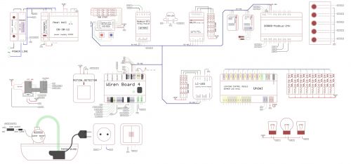
Example of connection devices
Schematic test stand -


