WB-M1W2 1-Wire to Modbus Temperature Measurement Module
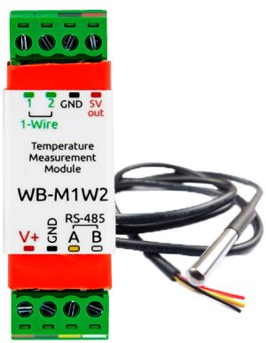
WB-M1W2 is a compact bus coupler, designed for polling two digital 1-Wire
thermometers (DS18B20) via Modbus RTU Protocol on RS-485 bus.
Inputs
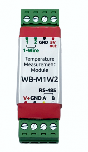
The module is powered by screw terminals V+ and GND, RS-485 line is connected to inputs A and B.
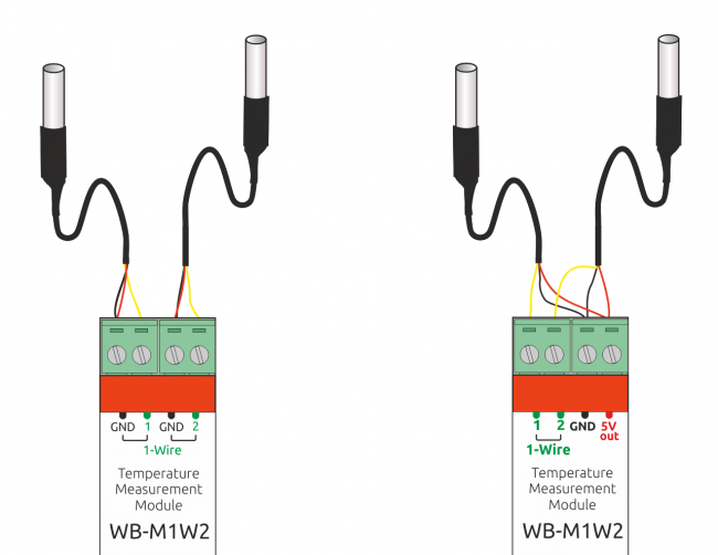
Version 1: Two external DS18B20 temperature sensors are connected via a parasitic power supply circuit, when the +5V and GND pins are connected to the GND terminal, the data output is connected to 1-Wire terminal 1 or 2.
Version 2: Two external temperature sensor DS18B20 is connected on an active power circuit, connect the sensor GND to the GND terminal, a data output connected to terminal 1 or 2 1-Wire, the sensor supply voltage is applied from the output to 5V out. In version 2 there is an additional protection of inputs 1-Wire.
Also, the device has an internal temperature sensor (NTC-thermistor).
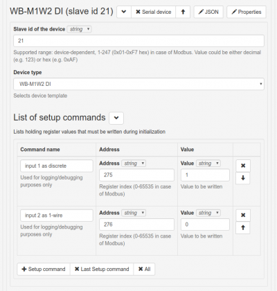
In firmware version 4.0.0 and higher, it is also possible to configure the 1-Wire inputs of the module as discrete or counting inputs.
Installation
The converter is installed in cable channels, boxes, soldering boxes. The recommended line length from the transmitter to the 1-Wire remote sensors is no more than 30 meters.
Specifications
| Option | Value |
|---|---|
| Power | |
| Supply voltage | 9 — 24 V DC |
| Power consumption |
0.1 W |
| эээTerminals and wire section | |
| Recommended wire cross-section with tips, mm2 | 0,75 — 1 |
| Length of the standard sleeve tips, mm | 8 |
| Torque of screws, N∙m | 0,2 |
| Sensors | |
| External sensor | Can connect two DS18B20 digital temperature sensors. |
| Internal sensor | Built-in NTC thermistor |
| Inputs (connect instead of external sensors) | |
| Number of digital inputs | 2 |
| Input type | Dry contact, uninsulated |
| Tension in the open position | 3.3 V |
| Control | |
| Management interface | RS-485 |
| Interface isolation | Uninsulated |
| Communication protocol | Modbus RTU, address is set by software, factory settings are indicated on the label |
| RS-485 interface parameters |
speed 9600 bps; data bits 8; parity N; stop bits 2; Starting from firmware version "'3.1.0"' parameters interfaces can be configured programmatically:
|
| dimensions | |
| Size |
|
| operating Conditions | |
| Air temperature | -40°C to +80°C |
| Relative humidity | up to 98%,without moisture condensate |
Additional functionality
Address change is broadcast (slave_id 0) team record (WRITE_SINGLE_REGISTER) to holding register with address 128 (0x80).
At adress 200 lies 6 bytes signature. The signature is unique for each device model and allows you to identify the model. To obtain the signatures necessary to fulfill READ_HOLDING_REGISTERS, address 200, length 6. Writing to this area of memory is not supported and error 3 is returned when attempting to write to an invalid location.
Register map
| Register/ address | Type | Read/ write | Default | Format | Purpose | Versions
insertions |
|---|---|---|---|---|---|---|
| 6 | input | R | 0x7FFF | °C × 16 (signed) | Temperature with built-in sensor | |
| 7 | input | R | 0x7FFF | °C × 16 (signed) | Temperature from the first external 1-Wire sensor | |
| 8 | input | R | 0x7FFF | °C × 16 (signed) | Temperature from second external 1-Wire sensor | |
| 20 | input | R | 0 | °C × 16 (signed) | Temperature from the first external 1-Wire sensor. In case of an error, the sensor retains the previous valid value (sensor status read from the discrete register 16). | starting with firmware 4.6.0 |
| 21 | input | R | 0 | °C × 16 (signed) | Temperature from the second external 1-Wire sensor. In case of an error, the sensor retains the previous valid value (sensor status read from the discrete register 17). | |
| 99 | holding | RW | 16 | 1 = 0.0625 C | (available from firmware version 3.10.0)
Suspicious value filter for 1-Wire sensors (85.000 C, 127.937 C). Values are discarded if the previous value differs from the suspect value by more than * 0.0625 C. Write 0 to disable the filter. |
3.10.0 |
| 104-105 | input | R | 32-bit unsigned int | |||
| 110 | holding | RW | 96 | baud rate / 100 | RS-485 port speed, "'divided by 100"'. Permissible speeds: 1200, 2400, 4800, 9600, 19200, 38400, 57600, 115200 | >3.1.0 |
| 111 | holding | RW | 0 | configure the RS-485 port parity bit. Valid values: 0 - no parity bit (none), 1 - odd (odd), 2 - even (even) | ||
| 112 | holding | RW | 2 | number of stop bits of RS-485 port. Valid values: 1, 2 | ||
| 120 (0x78) | holding | RW | 0 | other than 0 | write to the register causes a reset of the module without saving state | |
| 121 (0x79) | input | R | - | mV | current supply voltage of the module | |
| 128 (0x80) | holding | RW | 1 | The Modbus address of the device | ||
| 129 (0x81) | holding | RW | 0 | 0 or 1 | Go to bootloader mode | starting with firmware 4.5.0 |
| 200-206 | input | R | see Device signature | signature | ||
| 220-241 | input | R | __date__ _ _ time__ | the build date of the firmware | ||
| 245 | holding | RW | 216 | °C × 100 (signed) | Self-heating compensation of the built-in temperature sensor.
The register value is subtracted from the temperature measured by the built-in sensor (register 6) |
|
| 250-269 | input | R | string, null-terminated | firmware version | ||
| 270-271 | input | R | 32-bit unsigned int | unique identifier (S/N) | ||
| 275 | holding | RW | 0 | 0 or 1 | Input mode # 1: 0 - 1-wire, 1 - discrete input | >=4.0.0 |
| 276 | holding | RW | 0 | 0 or 1 | Input mode # 2: 0 - 1-wire, 1 - discrete input | |
| 277 | input | R | 16-bit unsigned int | Counter for input #1 | ||
| 278 | input | R | 16-bit unsigned int | Counter positives for the entrance №2 | ||
| 0 | discrete | R | 0 or 1 | Current state of input #1: 0 - open, 1 - closed on GND. If 1-wire mode is selected for input, the value is always 0. | ||
| 1 | discrete | R | 0 or 1 | Current state of input #2: 0 - open, 1 - closed on GND. If 1-wire mode is selected for input, the value is always 0. | ||
| 16 | discrete | R | 0 or 1 | Sensor polling status 1-Wire input no. 1: 0 - sensor not connected, 1 - sensor connected and correctly polled | starting with firmware 4.6.0 | |
| 17 | discrete | R | 0 or 1 | Sensor polling status 1-Wire input no. 2: 0 - sensor not connected, 1 - sensor connected and correctly polled |
Device signature
The 6-byte module signature is stored at address 200. The signature is unique for each model of Wiren Board devices and allows to identify the model by Modbus:
| Module | Signature |
|---|---|
| WB-M1W2 | WBMIR'0x00' |
Для получения сигнатуры нужно выполнить команду READ_HOLDING_REGISTERS по адресу 200 (длина 6 регистров). Запись в эту область памяти не поддерживается, при попытке записи в недопустимое место возвращается ошибка 3. Пустые места в тексте сигнатуры забиваются значением 0x00. Начиная с регистра 220 записана дата сборки прошивки, в формате "числоx00времяx00" в виде строки (пример: 'Jan 27 2017 17:01:13'). Длина записи — 21 регистр.
Работа преобразователя с контроллером Wiren Board
Для преобразователя WB-M1W2 в контроллере Wiren Board предусмотрен соответствующий шаблон WB-M1W2.
Описание каналов шаблона
| Название канала | Назначение |
|---|---|
| Input Voltage | Напряжение питания модуля |
| Internal Temperature Sensor | Температура внутреннего/внешнего цифрового датчика. Если датчик отсутствует или неисправен, его название выделяется красным цветом. |
| External Sensor 1 | Температура внешнего цифрового датчика, подключенного к порту 1. Если датчик отсутствует или неисправен, его название выделяется красным цветом. |
| External Sensor 2 | Температура внешнего цифрового датчика, подключенного к порту 2. Если датчик отсутствует или неисправен, его название выделяется красным цветом. |
| Serial NO | Серийный номер модуля, может потребоваться при обращении в техподдержку. |
С версии прошивки 4.0.0 преобразователь WB-M1W2 позволяет конфигурировать каждый из двух входов как дискретный вход. Режим входа задаётся в регистрах 275-276 (см. таблицу выше). В контроллерах Wiren Board этот режим настраивается через Setup-секцию драйвера.
Для отображения регистров, соответствующих дискретным входам, нужно выбрать шаблон "WB-M1W2 DI":
Каналы дискретных входов (не забудьте перевести входы в режим дискретных, как написано выше):
| Название канала | Назначение |
|---|---|
| Discrete Input 1 | Состояние входа 1. 0 - разомкнут, 1 - замкнут на GND |
| Discrete Input 2 | Состояние входа 2. 0 - разомкнут, 1 - замкнут на GND |
| Counter 1 | Счётчик срабатываний входа 1 |
| Counter 2 | Счётчик срабатываний входа 2 |
Управление модулем из командной строки
Программное обеспечение контроллера Wiren Board включает в себя утилиту modbus_client для работы с устройствами, подключенными к выходам RS-485, по протоколу Modbus, подробное описание команды находится на странице Modbus-client. Доступ к командной строке описан в статье SSH.
Пример чтения регистров
Проверим, верно ли, что мы подключились именно к модулю нужного типа. (Модуль wb-mqtt-serial должен быть предварительно остановлен). По адресу 200 хранится уникальная сигнатура длиной в 6 регистров. Прочтем 6 регистров, начиная с адреса 200, и преобразуем полученный ответ из шестнадцатеричных цифр в символьную строку:
echo  -e `modbus_client --debug -mrtu -pnone -s2 /dev/ttyAPP1 \
-a1 -t0x03 -r200 -c 6 | \
grep Data | sed -e 's/0x00/\\\x/g' -e 's/Data://' -e 's/\s//g'`
В результате выполнения команды получаем строку, например WBM1W2. В этом примере модуль WB-M1W2 имеет Modbus-адрес 1.
Обновление прошивки устройства
Начиная с новых версий микропрограмм устройства поддерживается функционал обновления прошивки (микропрограммы) по протоколу Modbus. Это дает возможность расширять функциональные возможности устройств и устранять ошибки в микропрограммном обеспечении непосредственно на месте монтажа. Подробнее о перепрошивке устройств рассказано в статье Загрузка прошивок на устройства Wiren Board. Список версий прошивок, поддерживающих обновление, а также устройств, для которых эта функция реализована, можно найти в статье Firmware_Changelog.
Изображения и чертежи устройства
По ссылкам ниже вы можете скачать изображения и чертежи устройства WB-M1W2.
Corel Draw 2018: WB_M1W2.cdr.zip
Corel Draw PDF: WB_M1W2.cdr.pdf
Autocad 2013 DXF: WB_M1W2.dxf.zip
Autocad PDF: WB_M1W2.pdf


