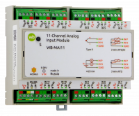
WB-MAI11 Modbus Analog Inputs/en
Purpose
The analog input module is designed for:
- voltage measurement;
- current measurement;
- resistance measurements on two-wire and three-wire circuits;
- temperature measurements using thermocouples or resistance thermometers;
- signal measurements from ratiometric sensors or variable resistors;
- connection of dry contact and open collector type signals.
The input mode is selected when configuring the instrument. No additional external load/pull-up resistors are required. The device allows you to connect up to 22 different sensors at the same time.
Design: housing on DIN-rail (width 6 units). Supply voltage 12 – 24V.
The module is controlled from the controller or PC via RS-485 bus by Modbus commands.
Specifications
| Parameter | Value |
|---|---|
| Power | |
| Supply voltage | 12 V – 24 V |
| measurement Channels | |
| Number of channels | 11 differential or 22 normal |
| Voltage measurement | -5 – 5 V differential mode
0 – 5 V normal operation |
| Current measurement | 0 – 20 mA |
| Resistance measurement | 0 – 5000 Ohms |
| Types of thermocouples supported | K |
| Types of resistance thermometers supported | Rt50, Pt100, Pt500, Pt1000, 50P, 100P, 500P, 1000P, 50M, 100M, 500M, 1000M, Ni100, Ni500, NI1000 |
| Voltage measurement error | ±0.2% |
| Current measurement error | ±0.2% |
| Error in the measurement of resistance | ±0.1% for INxP inputs
±1% for INxN inputs ±(0.1% + 0.003·Rw) for three-wire circuit |
| Control | |
| Management interface | RS-485 |
| Interface isolation | Galvanically isolated from measuring circuits |
| Communication protocol | Modbus RTU, address is set by software, factory settings are indicated on the label |
| RS-485 interface parameters | Default speed of 9600 bps; data bits 8; parity N; stop bits 2.
Interface parameters can be configured programmatically:
|
| Ready for operation after power supply | 1 c |
| dimensions | |
| Size | 106.25 x 90.2 x 57.5 mm |
| operating Conditions | |
| Air temperature | |
| Relative humidity | up to 98%, without condensation |
Connection diagrams
The module is made in a plastic case and is designed for installation in a mounting box on a DIN rail.
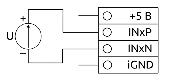
Fig. 1 shows the connection diagram of the sensor with the output type "voltage" in differential mode. This scheme is suitable for sensors whose output voltage can take negative values. Allows you to measure voltages from -5 to 5 V.
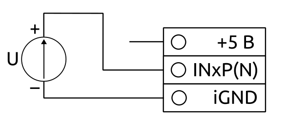 Fig. 2 shows the voltage measurement circuit relative to the common wire. This scheme allows you to measure only positive voltages from 0 to 5 V. It is possible to connect two sensors to one input.
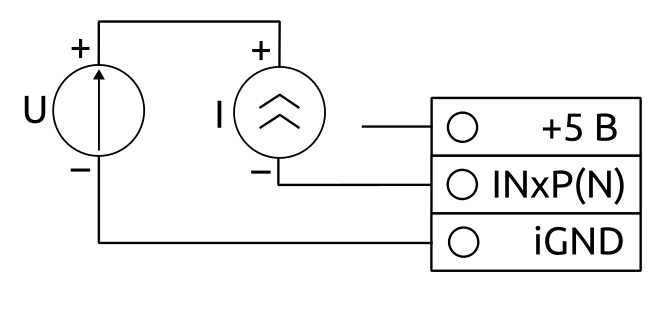 Fig.3 shows the connection diagram of sensors with a current output of 0-20 mA (4-20 mA). Load resistors with a nominal value of 100 Ω built in the device and connect via the software, the configuration process of the device. It is possible to connect two sensors to one input.
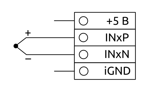 Fig. 4 shows the K-type thermocouple connection diagram. For correct detection of the absence of thermocouple input filter capacitors are discharged short-term (several µs) pulses with built-in resistors 100 Ohms. It is necessary to keep this in mind, if you connect another source of EMF instead of a thermocouple. The capacitors are only discharged in the "Standard sensors" mode when one of the supported thermocouples is selected. In basic modes, no discharge is performed.
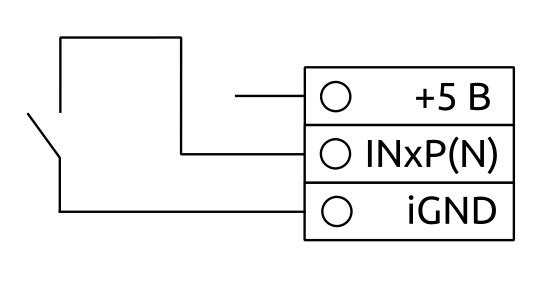 For rice. 5 shows the connection diagram of the sensors of the dry contact or resistance measurement on a two-wire circuit (shown by the dotted line). When using a two-wire circuit, the resistance of the wires is included in the measurement result. Due to the internal features of the INxP input device, the accuracy of the resistance measurement is greater than that of the INxN inputs. This should be taken into account when connecting the sensors. It is possible to connect two sensors to one input.
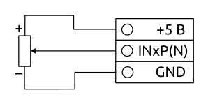 Fig. 6 is the scheme of connection of ratiometric sensors or variable resistors. In this mode, the signal from the sensor is measured as a percentage - from 0% (GND level) to 100% (+5V level). It is possible to connect two sensors to one input.
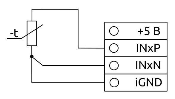 Fig. 7 shows a diagram of the resistance measurement of the three-wire circuit. In this mode, the resistance of the wires has almost no effect on the measurement result, provided that all the wires to the sensor are the same. The absolute effect of wire resistance on the final result is 0.003 Rw as opposed to 2Rw (Rw is the resistance of one wire to the sensor) in a two-wire circuit.
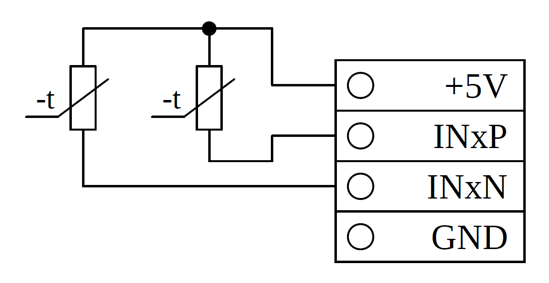 Fig. 8 shows a diagram of the resistance measurement using the current measurement. This circuit is used to connect an NTC thermistor. In this mode, the device can measure resistance in a wide range - from 150 Ohms to 1 MW. But keep in mind that the lower the resistance of the NTC, the greater the current in the circuit and self-heating NTC (as opposed to the circuits in Fig. 5 and Fig.7, where the current in the circuit is constant regardless of resistance). Therefore, the device artificially reduces the input polling rate depending on the current NTC resistance to compensate for self-heating. It is possible to connect two NTC to one input, but in this case, the polling rate is reduced, because during the survey of one, the current goes through both NTC, which leads to an increase in idle time to compensate for self-heating. To improve the accuracy of high resistance measurements, it is recommended to select the lowest possible data rate - 20 SPS.
Possible combinations of sensors to a single login
Two sensors can be connected to the same input with the following restrictions:
- If the channel INxP / off, channel, INxN should also be turned off
- If the channel INxP has a differential type configuration for channel INxN ignored
- Channel INxN may not have a differential type
- If the INxP channel is set to current measurement mode, the INxN channel must also be set to current measurement or disabled
- If the INxP channel is set to resistance or voltage measurement mode, the INxN channel must also be set to resistance or voltage measurement
- If the channel is configured to INxP mode of resistance measurement using the current measurement, and the channel INxN also have this mode or turned off
Channel settings INxP override the channel settings INxN. If the above conditions are not met, the INxN channel settings are ignored and the channel is disabled. Table 2 shows the possible sensor combinations for a single input.
| inxp channel connection Diagram | Possible inxn circuit | |||||||
|---|---|---|---|---|---|---|---|---|
| Figure 1 | Figure 2 | Figure 3 | Figure 4 | Figure 5 | Figure 6 | Figure 7 | Figure 8 | |
| Figure 1
The measurement of the voltage in differential mode |
||||||||
| Figure 2
Voltage measurement |
V | V | V | |||||
| Figure 3
Current measurement |
V | |||||||
| Figure 4
The connection of the thermocouple |
||||||||
| Figure 5
Connection of "dry contact" sensors and resistance measurement according to two-wire scheme |
V | V | V | |||||
| Figure 6
Connection of ratiometric sensors |
V | V | V | |||||
| Figure 7
Resistance measurement by three-wire circuit |
||||||||
| Figure 8
Resistance measurement using the current measurement |
V | |||||||
Description of Modbus registers
All modbus registers of the device are divided into 3 groups:
- Device settings
- The setting of the measurement channels
- Measured value
The register map is shown in table 3. 'X' in the register address is the entry number from 1 to 11 (0x1 to 0xB).
| Hex address | Dec address | Type | Read-write | Default | Format | Purpose |
|---|---|---|---|---|---|---|
| Device parameters | ||||||
| 0x006E | 110 | holding | RW | 96 | baud rate / 100 | RS-485 port speed, divided by 100. Allowable speed: 1200, 2400, 4800, 9600, 19200, 38400, 57600, 115200 |
| 0x006F | 111 | holding | RW | 0 | 0, 1, 2 | Configure the RS-485 port parity bit. Valid values: 0 - no parity bit (none), 1 - odd (odd), 2 - even (even) |
| 0x0070 | 112 | holding | RW | 2 | 1, 2 | Number of stop bits of RS-485 port. Valid values: 1, 2 |
| 0x0078 | 120 | holding | RW | 0 | otрук than 0 | Restart. Writing to the register causes the module restart without saving state |
| 0x0080 | 128 | holding | RW | 1 | Device Modbus-address | |
| 0x00C8 - 0x00CE | 200 - 206 | input | R | {'M','A','I',0,0,0} | Signature | |
| 0x00DC - 0x00F1 | 220 - 241 | input | R | __date__ __time__ | Firmware build date | |
| 0x00FA - 0x010D | 250 - 269 | input | R | string, null-terminated | Firmware version | |
| 0x010A - 0x010F | 266 - 271 | input | R | Unique identifier(S/N) | ||
| The setting of the measurement channels | ||||||
| 0xX400 | 4096·X + 1024 | holding | RW | 0 | Тable 4, table 5 | Type of sensor connected to INxP channel or to INx in differential mode (see tables 4 and 5) |
| 0xX401 | 4096·X + 1025 | holding | RW | 0 | Table 4, table 5 | Type of sensor connected to the INxN channel (see tables 4 and 5) |
| 0xX402 | 4096·X + 1026 | holding | RW | 0 | 0, 20, 45, 90, 175, 330, 600, 1000 | Data rate for INxP or INx channels in differential mode, SPS. 0 - channel is off |
| 0xX403 | 4096·X + 1027 | holding | RW | 0 | 0, 20, 45, 90, 175, 330, 600, 1000 | Data rate for INxN channels, SPS. 0 - channel off |
| 0xX404 | 4096·X + 1028 | holding | RW | 0 | 0 - 50 | Number of continuous measurements for INxP or INx channels in differential mode |
| 0xX405 | 4096·X + 1029 | holding | RW | 0 | 0 - 50 | Number of continuous measurements for INxN channels |
| 0xX406 | 4096·X + 1030 | holding | RW | 0 | 0 - 65000 | Characteristic time of lowpass filter for INxP or INx channels in differential mode, ms |
| 0xX407 | 4096·X + 1031 | holding | RW | 0 | 0 - 65000 | The characteristic time lowpass filter for INxN channels, ms |
| 0xX408 | 4096·X + 1032 | holding | RW | 0 | 16-bit signed int | The lower limit of the measuring range of the active sensor channels INx INxP or in differential mode |
| 0xX409 | 4096·X + 1033 | holding | RW | 0 | 16-bit signed int | The lower limit of the measuring range of the active sensor for INxN channels |
| 0xX40A | 4096·X + 1034 | holding | RW | 1000 | 16-bit signed int | The upper limit of the measuring range of the active sensor channels INx or INxP in differential mode |
| 0xX40B | 4096·X + 1035 | holding | RW | 1000 | 16-bit signed int | The upper limit of the measuring range of the active sensor INxN channels |
| 0xX40C | 4096·X + 1036 | holding | RW | 0 | 0 (авто), 1, 2, 4, 8, 16, 32, 64, 128 | Gain factor for INxP or INx channels in differential mode |
| 0xX40D | 4096·X + 1037 | holding | RW | 0 | 0 (авто), 1, 2, 4, 8, 16, 32, 64, 128 | The gain factor for INxN channels |
| Measured values | ||||||
| 0xX500 | 4096·X + 1280 | input | R | 0 | 32-bit signed int | Measured value for inxp or differential INX channel |
| 0xX502 | 4096·X + 1282 | input | R | 0 | 32-bit signed int | The measured value for INxN channel |
| 0xX504 | 4096·X + 1284 | input | R | 0 | 16-bit signed int | Converted to physical quantity value for inxp channel or differential INx channel |
| 0xX505 | 4096·X + 1285 | input | R | 0 | 16-bit signed int | Converted into physical quantity value for channel INxN |
| 0xX506 | 4096·X + 1286 | input | R | 1 | 16-bit signed int | The current gain factor for channel INxP or differential channels INx |
| 0xX507 | 4096·X + 1287 | input | R | 1 | 16-bit signed int | The current gain factor for channel INxN |
| 0x0600 | 1536 | input | R | 0 | 16-bit signed int | Terminal voltage +5V, мВ |
| 0x0601 | 1537 | input | R | 0 | 16-bit signed int | Temperature inside the device, °C·100 |
Since each input supports and differential (scheme in Fig. 1,4,7) and normal mode (scheme in Fig. 2,3,5,6) operation, the sensor type is set for inxp and INxN inputs separately in the respective registers 0xX400 и 0xX401, where X is the input number from 1 to 11 in hexadecimal (0x1 to 0xB).
Если для канала установлен автоматический коэффициент усиления, скорость опроса канала может быть снижена из-за необходимости производить несколько измерений для подбора коэффициента усиления.
Для нормального режима работы канала доступны только коэффициенты усиления 1, 2 и 4.
Если для входа INxP установлен дифференциальный режим, значение регистров конфигурации входов INxN игнорируются. Для входов INxN может быть установлен только нормальный режим.
Описание режимов работы устройства
Устройство позволяет для каждого входа настроить следующие режимы работы:
- Измерение напряжения относительно +5В (в дифференциальном или нормальном режиме)
- Измерение напряжения (в дифференциальном или нормальном режиме)
- Измерение сопротивления (в дифференциальном или нормальном режиме)
- Измерение тока (только в нормальном режиме)
- Измерение сопротивления через измерение тока (только в нормальном режиме)
В таблице 4 приведено полное описание всех возможных режимов работы. Данные режимы являются "базовыми", измерение сигналов со стандартных датчиков основано на них.
В регистры "тип датчика" (0xX400, 0xX401) для каждого входа могут быть занесены коды из таблицы 4 либо из таблицы 5. Для измерения нестандатных величин можно выбрать тип входа и диапазон измерения вручную из таблицы 4.
| Тип
измеряемого сигнала |
Режим входа | Код
HEX |
Код
DEC |
Описание | Коэффициент
усиления |
Диапазон измерения | Погрешность | Формат
выходных данных |
|---|---|---|---|---|---|---|---|---|
| Измерение
напряжения относительно +5В |
Нормальный | 0x0000 | 0 | Измерение напряжения с ратиометрических датчиков (схема на рис. 6)
Измерение напряжения от 0 до 5В (схема на рис. 2) |
1 | 0...(+5V) | ±0.1% | % · 100 |
| 2 | 0...(+5V / 2) | |||||||
| 4 | 0...(+5V / 4) | |||||||
| Дифференциальный | 0x0100 | 256 | Измерение напряжения в дифференциальном режиме от -5 до 5 В (схема на рис. 1) | 1 | ± (+5V) | ±0.1% | ||
| 2 | ± (+5V / 2) | |||||||
| 4 | ± (+5V / 4) | |||||||
| Измерение
напряжения |
Нормальный | 0x0001 | 1 | Измерение напряжения в нормальном режиме от 0 до 2 В (схема на рис. 2) | 1 | 0...2048 мВ | ±0.2% | мВ · 100 |
| 2 | 0...1024 мВ | |||||||
| 4 | 0...512 мВ | |||||||
| Дифференциальный | 0x0101 | 257 | Измерение напряжения в дифференциальном режиме от -2 до 2 В (схема на рис. 1)
Измерение напряжения с термопары (схема на рис. 4) |
1 | ± 2048 мВ | ±0.2% | ||
| 2 | ± 1024 мВ | |||||||
| 4 | ± 512 мВ | |||||||
| 8 | ± 256 мВ | ±0.25% | ||||||
| 16 | ± 128 мВ | |||||||
| 32 | ± 64 мВ | |||||||
| 64 | ± 32 мВ | |||||||
| 128 | ± 16 мВ | |||||||
| Измерение
сопротивления |
Нормальный
для входов INxP |
0x0002 | 2 | Измерение сопротивления по двухпроводной схеме (схема на рис. 5)
Подключение датчиков типа "сухой контакт" (схема на рис. 5) |
1 | 0...5000 Ом | ±0.1% | Ом · 100 |
| 2 | 0...2550 Ом | |||||||
| 4 | 0...1275 Ом | |||||||
| Нормальный
для входов INxN |
1 | 0...5100 Ом | ±1% номинальная
±6% максимальная | |||||
| 2 | 0...2550 Ом | |||||||
| 4 | 0...1275 Ом | |||||||
| Дифференциальный
(трехпроводная схема) |
0x0102 | 258 | Измерение сопротивления по трехпроводной схеме (схема на рис. 7) | 1 | 0...5000 Ом | ±0.1% | ||
| 2 | 0...2550 Ом | |||||||
| 4 | 0...1275 Ом | |||||||
| Измерение
тока |
Нормальный | 0x0003 | 3 | Измерение тока от 0 до 20 мА (схема на рис. 3) | 1 | 0...20.48 мА | ±0.2% | мА · 10000 |
| 2 | 0...10.24 мА | |||||||
| 4 | 0...5.12 мА | |||||||
| Измерение сопротивления
через измерение тока в цепи |
Нормальный | 0x0004 | 4 | Измерение сопротивления NTC-термистора (схема на рис. 8)
Ток в цепи идет только в момент опроса текущего входа, во время опроса остальных входов ток не идет, в отличие от режиме "измерение тока", где ток идет всегда. |
1 | 200 Ом .. 250 кОм | ±3% в конце диапазона
±1,5% в середине диапазона ±0.5% в начале диапазона |
Ом |
| 2 | 500 Ом .. 500 кОм | |||||||
| 4 | 1200 Ом .. 1 МОм |
Типы поддерживаемых стандартных датчиков
Поддерживаемые типы стандартных датчиков приведены в таблице 5. При использовании стандартных датчиков значения регистров 0xX40A и 0xX40B (коэффициент усиления) игнорируется. Стандартные датчики имеют код 0x1XXX.
| Код датчика
HEX |
Код датчика
DEC |
Описание | Коэффициент
усиления |
Формат
сырых данных |
Формат
пересчитанных данных |
Погрешность |
|---|---|---|---|---|---|---|
| Термоэлектрические преобразователи
Режим работы – измерение напряжения с термопары (схема на рис. 4) | ||||||
| 0x1000 | 4096 | ТХА (K) | 32 | мВ · 100 | °C · 10 | ±0.5 °С |
| Термометры сопротивления по двухпроводной схеме
Режим работы – измерение сопротивления по двухпроводной схеме (схема на рис. 5) | ||||||
| 0x1100 | 4352 | Pt 50 (α = 0,00385 °C -1) | 4 | Ом · 100 | °C · 10 | ±0.4 °С |
| 0x1101 | 4353 | Pt 100 (α = 0,00385 °C -1) | 4 | |||
| 0x1102 | 4354 | Pt 500 (α = 0,00385 °C -1) | 2 | ±0.25 °С | ||
| 0x1103 | 4355 | Pt 1000 (α = 0,00385 °C -1) | 1 | |||
| 0x1110 | 4368 | 50П (α = 0,00391 °C -1) | 4 | ±0.4 °С | ||
| 0x1111 | 4369 | 100П (α = 0,00391 °C -1) | 4 | |||
| 0x1112 | 4370 | 500П (α = 0,00391 °C -1) | 2 | ±0.25 °С | ||
| 0x1113 | 4371 | 1000П (α = 0,00391 °C -1) | 1 | |||
| 0x1120 | 4384 | 50М (α = 0,00428 °C -1) | 4 | ±0.35 °С | ||
| 0x1121 | 4385 | 100М (α = 0,00428 °C -1) | 4 | |||
| 0x1122 | 4386 | 500М (α = 0,00428 °C -1) | 4 | ±0.25 °С | ||
| 0x1123 | 4387 | 1000М (α = 0,00428 °C -1) | 2 | |||
| 0x1130 | 4400 | Ni 100 (α = 0,00617 °C -1) | 4 | |||
| 0x1131 | 4401 | Ni 500 (α = 0,00617 °C -1) | 2 | ±0.2 °С | ||
| 0x1132 | 4402 | Ni 1000 (α = 0,00617 °C -1) | 1 | |||
| Термометры сопротивления по трехпроводной схеме
Режим работы – измерение сопротивления по трехпроводной схеме (схема на рис. 7) | ||||||
| 0x1200 | 4608 | Pt 50 (α = 0,00385 °C -1) | 4 | Ом · 100 | °C · 10 | ±0.4 °С |
| 0x1201 | 4609 | Pt 100 (α = 0,00385 °C -1) | 4 | |||
| 0x1202 | 4610 | Pt 500 (α = 0,00385 °C -1) | 2 | ±0.25 °С | ||
| 0x1203 | 4611 | Pt 1000 (α = 0,00385 °C -1) | 1 | |||
| 0x1210 | 4624 | 50П (α = 0,00391 °C -1) | 4 | ±0.4 °С | ||
| 0x1211 | 4625 | 100П (α = 0,00391 °C -1) | 4 | |||
| 0x1212 | 4626 | 500П (α = 0,00391 °C -1) | 2 | ±0.25 °С | ||
| 0x1213 | 4627 | 1000П (α = 0,00391 °C -1) | 1 | |||
| 0x1220 | 4640 | 50М (α = 0,00428 °C -1) | 4 | ±0.35 °С | ||
| 0x1221 | 4641 | 100М (α = 0,00428 °C -1) | 4 | |||
| 0x1222 | 4642 | 500М (α = 0,00428 °C -1) | 4 | ±0.25 °С | ||
| 0x1223 | 4643 | 1000М (α = 0,00428 °C -1) | 2 | |||
| 0x1230 | 4656 | Ni 100 (α = 0,00617 °C -1) | 4 | |||
| 0x1231 | 4657 | Ni 500 (α = 0,00617 °C -1) | 2 | ±0.2 °С | ||
| 0x1232 | 4658 | Ni 1000 (α = 0,00617 °C -1) | 1 | |||
| Датчики с токовым выходом
Режим работы – измерение тока от 0 до 20 мА (схема на рис. 3) | ||||||
| 0x1300 | 4864 | от 0 до 5 мА | 4 | мА · 10000 | 0 мА = нижняя граница (регистры 0xX408 / 0xX409)
5 мА = верхняя граница (регистры 0xX40A / 0xX40B) |
±0.25 % |
| 0x1301 | 4865 | от 0 до 20 мА | 1 | мА · 10000 | 0 мА = нижняя граница (регистры 0xX408 / 0xX409)
20 мА = верхняя граница (регистры 0xX40A / 0xX40B) |
±0.25 % |
| 0x1302 | 4866 | от 4 до 20 мА | 1 | мА · 10000 | 4 мА = нижняя граница (регистры 0xX408 / 0xX409)
20 мА = верхняя граница (регистры 0xX40A / 0xX40B) |
±0.25 % |
| Датчики с выходом "напряжение" в нормальном режиме
Режим работы – измерение напряжения в нормальном режиме от 0 до 2 В (схема на рис. 2) | ||||||
| 0x1400 | 5120 | от 0 до 1 В | 2 | мВ · 100 | 0 В = нижняя граница(регистры 0xX408 / 0xX409)
1 В = верхняя граница (регистры 0xX40A / 0xX40B) |
±0.2 % |
| Датчики с выходом "напряжение" в дифференциальном режиме
Режим работы – измерение напряжения в дифференциальном режиме от -2 до 2 В (схема на рис. 1) | ||||||
| 0x1500 | 5376 | от -50 до 50 мВ | 32 | мВ · 100 | -50 мВ = нижняя граница(регистры 0xX408 / 0xX409)
50 мВ = верхняя граница (регистры 0xX40A / 0xX40B) |
±0.2 % |
| Датчики контактные (сухие)
Режим работы – измерение сопротивления по двухпроводной схеме (схема на рис. 5) | ||||||
| 0x1600 | 5632 | Сухой контакт | 1 | Ом · 100 | 0 - датчик разомкнут или отсутствует
1 - датчик замкнут |
|
| NTC термисторы
Режим работы - измерение сопротивления через измерение тока (схема на рис. 8) | ||||||
| 0x1700 | 5888 | NTC 10k (B = 3988 K) | 1 - 4 (авто) | Ом | °C · 10 | Ниже -40 °С: ±1 °С
От -40 до -20 °С: ±0.5 °С Выше -20 °С: ±0.25 °С |
Примеры конфигурации устройства
В таблице 6 приведено несколько примеров конфигурации устройства. Адреса регистров приведены для канала №1. Для использования других каналов адреса следует пересчитать в соответствии с таблицей 3.
В таблице заполнены только те ячейки, которые влияют на конфигурацию входа для измерения сигналов с указанных датчиков. В остальные регистры конфигурации следует записать "0".
| Адрес регистра | Примеры конфигураций для некоторых датчиков | |||
|---|---|---|---|---|
| Измерение температуры
термопарой K-типа (подключена к входу IN1). Схема на рис. 4 |
Измерение температуры
термометров сопротивления Pt1000 по трехпроводной схеме (подключен к входу IN1). Схема на рис. 7 |
Измерение сигнала с
датчика с токовым выходом 4-20 мА (подключен к входу IN1P). Схема на рис. 3 |
Измерение температуры
NTC-термистором 10 кОм, B = 3988 K. Схема на рис. 8 | |
| Регистры конфигурации | ||||
| 0x1400 | 0x1000 | 0x1203 | 0x1302 | 0x1700 |
| 0x1401 | ||||
| 0x1402 | 20 | 20 | 20 | 20 |
| 0x1403 | ||||
| 0x1404 | 0 | 0 | 0 | 0 |
| 0x1405 | ||||
| 0x1406 | 100 | |||
| 0x1407 | ||||
| 0x1408 | 800 | |||
| 0x1409 | ||||
| 0x140A | ||||
| 0x140B | ||||
| Регистры измеренных значений | ||||
| 0x1500 | Напряжение на термопаре, мВ · 100 | Сопротивление датчика, Ом · 100 | Ток, мА · 10000 | Сопротивление датчика, Ом |
| 0x1502 | ||||
| 0x1504 | Температура спая, °C · 10 | Температура датчика, °C · 10 | 100 - при токе 4 мА; 800 - при токе 20 мА
если значение не в диапазоне [100..800], датчик неисправен или отсутствует |
Температура датчкика, °C · 10 |
| 0x1505 | ||||
| 0x1506 | ||||
| 0x1507 | ||||
