WB-MCM16 Модуль счетных входов 16-канальный/en: различия между версиями
(Новая страница: «The module of discrete and counting inputs 16-channel WB-MCM16 is designed to connect signals of dry contact and open collector, connection of metering devices o…») |
|||
| (не показаны 22 промежуточные версии этого же участника) | |||
| Строка 1: | Строка 1: | ||
<languages/> | <languages/> | ||
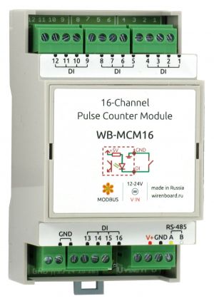
[[File:MCM16.JPG| | [[File:MCM16.JPG|альт=WB-MCM16 module|мини|414x414pcs|WB-MCM16 Module]] | ||
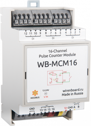
[[File:WB-MCM16 | [[File:Модуль WB-MCM16.png|альт=WB-MCM16 Module|мини|414х414пкс|WB-MCM16 Module, push terminals]] | ||
The model is discontinued. Recommended replacement - [[WB- | The model is discontinued. Recommended replacement - [[WB-MCM8_Модуль_счетных_входов_8-канальный/en|WB-MCM8]]. '''[https://wirenboard.com/en/product/WB-MCM8/ Buy WB-MCM8 in the online store]''' | ||
{{#vardefine:ProductFullName1| 16-channel pulse counting module WB-MCM16}} {{#vardefine:FileName1|WB-MCM16}} {{#vardefine:ProductName1|WB-MCM16}} | {{#vardefine:ProductFullName1| 16-channel pulse counting module WB-MCM16}} {{#vardefine:FileName1|WB-MCM16}} {{#vardefine:ProductName1|WB-MCM16}} | ||
| Строка 11: | Строка 11: | ||
connection of metering devices of water, electricity, gas, etc. with pulse outputs. | connection of metering devices of water, electricity, gas, etc. with pulse outputs. | ||
No pre-configuration of input modes is required. There is protection against overfilling of the pulse counter. | |||
Version: housing on DIN-rail (width 3 units). Supply voltage 12 – 24V | |||
The module is controlled from the controller or PC via the RS-485 bus by MODBUS commands, as well as by external buttons. | |||
== | ==Technical specifications== | ||
* 16 | * 16 digital inputs with pulse counting support with built-in voltage sources | ||
* | * Minimum pulse duration: 21ms, maximum pulse frequency: 25 Hz | ||
* | * Group galvanic isolation of inputs from RS-485 interface, up to 1.5 kV. | ||
* | * Supply voltage: 11 to 24 V. | ||
* | * Power consumption: 0.3 W. | ||
* | * Interface: RS485, Modbus RTU. | ||
* | * Save counter values when power is off | ||
* | * Led indication for power and data exchange | ||
* | * Install in the electrical panel on a DIN rail, housing width 3 DIN. | ||
{| class="wikitable" | {| class="wikitable" | ||
!colspan="2" | ''' | !colspan="2" | '''Terminals and wire section''' | ||
|- | |- | ||
|| | || Recommended wire cross-section with TSVI, mm<sup>2</sup>|| 0,75 — 1 | ||
|- | |- | ||
|| | || Length of the standard sleeve NSVE, mm || 8 (10 for adjusting screwless terminal blocks) | ||
|- | |- | ||
|| | || Torque of screws, N∙m || 0,2 (for screw terminals) | ||
|- | |- | ||
|} | |} | ||
==== | ====Operating conditions==== | ||
* | * Air temperature from -40°C to +50°C; | ||
* | * Relative humidity up to 92%,without moisture condensation. | ||
==== | ==== Connection ==== | ||
The module is made in a plastic case and is designed for installation in a mounting box on a DIN rail. | |||
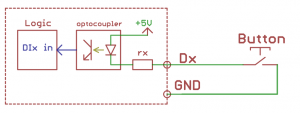
The scheme of inputs is shown in the figure. The terminal is supplied ~ 4.5 V, when the earth current flows a small (1.5 mA), causing the operation of the input. | |||
[[ | [[File:DI.png|300px|thumb|none|Digital inputs]] | ||
To be done... | To be done... | ||
== | == Management == | ||
See [[Протокол Modbus/en| Modbus protocol]] | |||
==== | ==== Bus parameters. ==== | ||
Speed 9600 bit/s, data - 8 bit, | |||
parity – no, stop bit - 2. | |||
=== | === Modbus commands supported by the device === | ||
| Строка 78: | Строка 78: | ||
|- | |- | ||
| | |READ_HOLDING_REGISTERS || 4 | ||
|- | |- | ||
| Строка 93: | Строка 93: | ||
|} | |} | ||
Address change is broadcast (slave_id 0) team record (WRITE_SINGLE_REGISTER) to holding register with address 128 (0x80). | |||
The address 200 has a 6-byte signature. The signature is unique for each device model and allows you to identify the model. | |||
To obtain the signatures necessary to fulfill READ_HOLDING_REGISTERS address 200 length 6. | |||
Writing to this area of memory is not supported and error 3 is returned when attempting to write to an invalid location. | |||
== | == Register map == | ||
Текущая версия на 17:49, 27 ноября 2019
The model is discontinued. Recommended replacement - WB-MCM8. Buy WB-MCM8 in the online store
Purpose
The module of discrete and counting inputs 16-channel WB-MCM16 is designed to connect signals of dry contact and open collector, connection of metering devices of water, electricity, gas, etc. with pulse outputs.
No pre-configuration of input modes is required. There is protection against overfilling of the pulse counter.
Version: housing on DIN-rail (width 3 units). Supply voltage 12 – 24V
The module is controlled from the controller or PC via the RS-485 bus by MODBUS commands, as well as by external buttons.
Technical specifications
- 16 digital inputs with pulse counting support with built-in voltage sources
- Minimum pulse duration: 21ms, maximum pulse frequency: 25 Hz
- Group galvanic isolation of inputs from RS-485 interface, up to 1.5 kV.
- Supply voltage: 11 to 24 V.
- Power consumption: 0.3 W.
- Interface: RS485, Modbus RTU.
- Save counter values when power is off
- Led indication for power and data exchange
- Install in the electrical panel on a DIN rail, housing width 3 DIN.
| Terminals and wire section | |
|---|---|
| Recommended wire cross-section with TSVI, mm2 | 0,75 — 1 |
| Length of the standard sleeve NSVE, mm | 8 (10 for adjusting screwless terminal blocks) |
| Torque of screws, N∙m | 0,2 (for screw terminals) |
Operating conditions
- Air temperature from -40°C to +50°C;
- Relative humidity up to 92%,without moisture condensation.
Connection
The module is made in a plastic case and is designed for installation in a mounting box on a DIN rail. The scheme of inputs is shown in the figure. The terminal is supplied ~ 4.5 V, when the earth current flows a small (1.5 mA), causing the operation of the input.
To be done...
Management
See Modbus protocol
Bus parameters.
Speed 9600 bit/s, data - 8 bit, parity – no, stop bit - 2.
Modbus commands supported by the device
| Command | command (dec) |
|---|---|
| READ_DISCRETE_INPUTS | 2 |
| READ_HOLDING_REGISTERS | 4 |
| READ_HOLDING_REGISTERS | 3 |
| WRITE_SINGLE_REGISTER | 6 |
| WRITE_MULTI_REGISTERS | 16 |
Address change is broadcast (slave_id 0) team record (WRITE_SINGLE_REGISTER) to holding register with address 128 (0x80).
The address 200 has a 6-byte signature. The signature is unique for each device model and allows you to identify the model. To obtain the signatures necessary to fulfill READ_HOLDING_REGISTERS address 200 length 6. Writing to this area of memory is not supported and error 3 is returned when attempting to write to an invalid location.
Register map
| Регистр / адрес (dec) | тип | чтение/запись | формат | назначение |
|---|---|---|---|---|
| 0 | discrete input | R | 1 or 0 | состояние входа #1 |
| ... | ||||
| 15 | discrete input | R | 1 or 0 | состояние входа #16 |
| 20 - 23 | input/holding | R | 64-битное целое без знака. Big-endian порядок байт. 4 регистра на канал | счетчик импульсов на входе #1. |
| ... | ||||
| 80 - 83 | input/holding | R | 64-битное целое без знака. Big-endian порядок байт. 4 регистра на канал | счетчик импульсов на входе #16. |
| 100 | holding | RW | регистр сброса. Запись 1 в регистр приводит к сбросу всех счётчиков на всех каналах | |
| 200-206 | input/holding | R | {'W','B','C',M','1','6'} | сигнатура |
| 220-243 | input/holding | R | __date__ __time__ | дата сборки прошивки |
| 128 | holding | W | 1-247 | адрес Modbus |
Назад к списку периферийных устройств
Изображения и чертежи устройства
По ссылкам ниже вы можете скачать изображения и чертежи устройства WB-MCM16.
Corel Draw 2018: WB-MCM16.cdr.zip
Corel Draw PDF: WB-MCM16.cdr.pdf
Autocad 2013 DXF: WB-MCM16.dxf.zip
Autocad PDF: WB-MCM16.pdf


