WB-MIR v1 - Modbus IR Remote Control/en: различия между версиями
(Новая страница: «WB-MIR v1 - Modbus IR Remote Control») |
(Новая страница: «On the example of a fully functional module, consider the main controls of the module and their purpose. {| class="wikitable" ! The name of the control !Purpose |…») |
||
| (не показано 25 промежуточных версий этого же участника) | |||
| Строка 1: | Строка 1: | ||
<languages> | <languages> | ||
{{DISPLAYTITLE:Устройство IR-управления WB-MIR v1}} | <!--{{DISPLAYTITLE:Устройство IR-управления WB-MIR v1}}--> | ||
''' | '''This page describes the device WB-MIR v1, discontinued in 11.2017. Direct replacement is improved module [[WB-MIR v2 - Modbus IR Remote Control/en|WB-MIR v2]]''' | ||
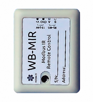
[[File:WB-MIR-sample.png |300px|thumb|right| | [[File:WB-MIR-sample.png |300px|thumb|right| WB-MIR Module]] | ||
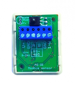
[[File:Wb-MIR-sample_internals.png |300px|thumb|right| | [[File:Wb-MIR-sample_internals.png |300px|thumb|right| Module internals. Contact labels are visible on the connectors]] | ||
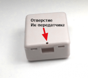
[[File:Wb-mir-ir-transmitter.png |300px|thumb|right| | [[File:Wb-mir-ir-transmitter.png |300px|thumb|right| IR transmitter hole on the back of the module]] | ||
Learning module with IR transceiver for IR control of various devices, including air conditioners, TVs, etc. | |||
The module is controlled from the controller or PC via RS-485 bus by Modbus commands. | |||
== | == Inputs== | ||
The module is powered by V+ and GND screw terminals, the RS-485 line is connected to inputs A and B. the DS18B20 External temperature sensor is connected via a parasitic power supply circuit, when the +5V and GND terminals are connected and connected to the GND terminal, the data output is connected to the 1-W terminal. | |||
D | D some models have an internal temperature sensor DS18B20 in the case TO-92, soldered in the upper left part of the module Board (the top view of the sensor housing is printed in this place by silkscreen). | ||
== | ==Installation== | ||
The module is mounted on the air conditioner on a double-sided tape so that a small hole of the emitting diode on the reverse side would be located opposite the IR receiver of the air conditioner, without closing the receiver from the main console of the device. The position is selected experimentally due to the huge variety of designs of air conditioning housings. The same applies to any household devices controlled by IR channel. | |||
== | == Specifications == | ||
{| class="wikitable" | {| class="wikitable" | ||
! style="text-align: center;" | | ! style="text-align: center;" | Option | ||
! style="text-align: center;" | | ! style="text-align: center;" | Value | ||
|- | |- | ||
! colspan="2" | | ! colspan="2" |Power | ||
|- | |- | ||
| | |Supply voltage | ||
|9 — 24 | |9 — 24 V DC | ||
|- | |- | ||
| | |Power consumption | ||
| | | | ||
0.1 | 0.1 W | ||
|- | |- | ||
| | |Transmitter range | ||
| < | | < 1m | ||
|- | |- | ||
| | | External sensor | ||
| | | Digital temperature sensor DS18B20 can be connected. | ||
|- | |- | ||
! colspan="2" | | ! colspan="2" |Control | ||
|- | |- | ||
| | |Management interface | ||
|RS-485 | |RS-485 | ||
|- | |- | ||
| | |Interface isolation | ||
| | |Uninsulated | ||
|- | |- | ||
| | |Communication protocol | ||
|Modbus RTU, | |Modbus RTU, address is set by software, factory settings are indicated on the label | ||
|- | |- | ||
| | |RS-485 interface parameters | ||
| | | | ||
speed 9600 bps; data bits 8; parity N; stop bits 2; | |||
Starting from firmware version '''3.1.0''' parameters interfaces can be configured programmatically: | |||
* | *Speed: 1200, 2400, 4800, 9600 (default), 19200, 38400, 57600, 115200 bit/s <br>([[UART_Communication_Settings/en|configure RS-485 communication parameters for wiren Board modbus devices]]) | ||
* | *Data: 8 bit | ||
* | *Parity check: none (default), 1 - odd (odd), 2 - even (even) | ||
* | *Stop bits: 2 (default), 1 | ||
|- | |- | ||
! colspan="2" | | ! colspan="2" |dimensions | ||
|- | |- | ||
| | | Size | ||
| 45x35x14 | | 45x35x14 mm | ||
|- | |- | ||
! colspan="2" | | ! colspan="2" |Operating conditions | ||
|- | |- | ||
| | | Air temperature | ||
| - | | -40°C to +80°C | ||
|- | |- | ||
| | | Relative humidity | ||
| | | up to 98%,without moisture condensate | ||
|} | |} | ||
== | == Learning and using the module == | ||
Detailed description and use of the module, and a map of the registers is described in section [[WB-MSx_Consumer_IR_Manual/en|how to work with the IR receiver in the WB-MS WB-MSW, WB-MIR devices]]. | |||
== | == Additional functionality== | ||
''' | '''Address change''' is broadcast (slave_id 0) team record (WRITE_SINGLE_REGISTER) to holding register with address 128 (0x80). | ||
The 6-byte module signature is stored at address 200. The signature is unique for each model of Wiren Board devices and allows to identify the model. | |||
To obtain the signatures necessary to fulfill READ_HOLDING_REGISTERS address 200 length 6. | |||
Writing to this area of memory is not supported and error 3 is returned when attempting to write to an invalid location. | |||
== | == Register map == | ||
Described in detail in [[WB-MSx_Consumer_IR_Manual/en|how to work with the IR receiver in the WB-MS WB-MSW, WB-MIR devices ]]. | |||
{| class="wikitable" | {| class="wikitable" | ||
! rowspan="2" | | ! rowspan="2" |Register/ address | ||
! rowspan="2" | | ! rowspan="2" |Type | ||
! rowspan="2" | | ! rowspan="2" |Read/ write | ||
! rowspan="2" | | ! rowspan="2" |Default | ||
! rowspan="2" | | ! rowspan="2" |Format | ||
! rowspan="2" | | ! rowspan="2" |Purpose | ||
! | !Versions | ||
insertions | |||
|- | |- | ||
! | ! | ||
| Строка 106: | Строка 106: | ||
|0x7FFF | |0x7FFF | ||
|°C × 16 (signed) | |°C × 16 (signed) | ||
| | |Temperature with built-in 1-Wire sensor | ||
| | | | ||
|- | |- | ||
| Строка 114: | Строка 114: | ||
|0x7FFF | |0x7FFF | ||
|°C × 16 (signed) | |°C × 16 (signed) | ||
| | |Temperature from external 1-Wire sensor | ||
| | | | ||
|- | |- | ||
| Строка 130: | Строка 130: | ||
|96 | |96 | ||
|baud rate / 100 | |baud rate / 100 | ||
| | |RS-485 port speed, "'divided by 100"'. Permissible speeds: 1200, 2400, 4800, 9600, 19200, 38400, 57600, 115200 | ||
| rowspan="3" |>3.1.0 | | rowspan="3" |>3.1.0 | ||
|- | |- | ||
| Строка 138: | Строка 138: | ||
|0 | |0 | ||
| | | | ||
| | |configure the RS-485 port parity bit. Valid values: 0 - no parity bit (none), 1 - odd (odd), 2 - even (even) | ||
|- | |- | ||
|112 | |112 | ||
| Строка 145: | Строка 145: | ||
|2 | |2 | ||
| | | | ||
| | |number of stop bits of RS-485 port. Valid values: 1, 2 | ||
|- | |- | ||
| | | | ||
| Строка 159: | Строка 159: | ||
|RW | |RW | ||
|0 | |0 | ||
| | |other than 0 | ||
| | |write to the register causes a reset of the module without saving state | ||
| | | | ||
|- | |- | ||
| Строка 168: | Строка 168: | ||
| - | | - | ||
|mV | |mV | ||
| | |current supply voltage of the module | ||
| | | | ||
|- | |- | ||
| Строка 176: | Строка 176: | ||
|1 | |1 | ||
| | | | ||
|Modbus | |The Modbus address of the device | ||
| | | | ||
|- | |- | ||
| Строка 182: | Строка 182: | ||
|input | |input | ||
|R | |R | ||
| | |see [[Sensors Modbus Management|device Signature]] | ||
| | | | ||
| | |signature | ||
| | | | ||
|- | |- | ||
| Строка 191: | Строка 191: | ||
|R | |R | ||
| | | | ||
|__date__ | |__date__ _ _ time__ | ||
| | |the build date of the firmware | ||
| | | | ||
|- | |- | ||
| Строка 199: | Строка 199: | ||
|R | |R | ||
| | | | ||
| | |string, null-terminated | ||
| | |firmware version | ||
| | | | ||
|- | |- | ||
| Строка 208: | Строка 208: | ||
| | | | ||
|32-bit unsigned int | |32-bit unsigned int | ||
| | |unique identifier (S/N) | ||
| | | | ||
|} | |} | ||
== | == Device signature == | ||
The 6-byte module signature is stored at address 200. The signature is unique for each model of Wiren Board devices and allows to identify the model by Modbus: | |||
{| class="wikitable" | {| class="wikitable" | ||
! style="font-weight: bold;" | | ! style="font-weight: bold;" | Module | ||
! style="font-weight: bold;" | | ! style="font-weight: bold;" | Signature | ||
|- | |- | ||
| WB-MIR | | WB-MIR | ||
| Строка 224: | Строка 224: | ||
|} | |} | ||
To get the signature of a device you need to run command READ_HOLDING_REGISTERS at 200 (length of 6 registers). Writing to this area of memory is not supported, and error 3 is returned when attempting to write to an invalid location. Empty spaces in the signature text are clogged with the value 0x00. | |||
Starting from register 220, the firmware build date is recorded, in the format ''number'''x00'''time'''x00''''' as a string (example: 'Jan 27 2017 17:01:13'). The length of the record is 21 registers. | |||
== | == Module management from the web interface == | ||
At the moment, to connect the module WB-MIR, there are two templates: '''WB-MIR''' and '''WB-MIR (simple)'''. Template '''WB-MIR''' provides a complete set of functions of the module from the web interface, including training, and a simplified version '''WB-MIR (simple)''' can be used with the already trained remote control and contains a much smaller number of controls. | |||
{| class="wikitable" | {| class="wikitable" | ||
|[[File:Web_wb_mir.png |600px|thumb|right| | |[[File:Web_wb_mir.png |600px|thumb|right|WB-MIR Web interface]] | ||
|[[File:Web-wb-mir-simple.png|300px|thumb|right| | |[[File:Web-wb-mir-simple.png|300px|thumb|right|Simplified WB-MIR web interface]] | ||
|} | |} | ||
<div class="mw-translate-fuzzy"> | |||
On the example of a fully functional module, consider the main controls of the module and their purpose. | |||
{| class="wikitable" | {| class="wikitable" | ||
! | ! The name of the control | ||
! | !Purpose | ||
|- | |- | ||
|Input Voltage|| | |Input Voltage||module supply Voltage | ||
|- | |- | ||
|Learn to RAM|| | |Learn-to-RAM||Write the IR signal in the operational buffer (see section [[#Operational mode|Operational mode]]). For learning, the control is turned ON, after learning — OFF. | ||
|- | |- | ||
|Play from RAM|| | |Play from RAM||Play the IR signal from the operating buffer (see [[#Operating mode|Operating mode]]). | ||
|- | |- | ||
|Learn to ROMx|| | |Learn to ROMx||IR signal Recording ACC. the cell of the ROM (see section [[#DC mode|DC mode]]). For learning, the control is turn ON position, after learning — OFF. | ||
|- | |- | ||
|Play from ROMx|| | |Play from ROMx||Play IR signal from resp. ROM cells (see [[#Constant mode|Constant mode]]]). For learning, the control is transferred to THE on position, after learning — OFF. | ||
|- | |- | ||
|ROMx -> RAM|| | |ROMx -> RAM||Copy data from ACC. ROM cells to the online buffer for editing (see [[#Constant mode|Constant mode]]). For editing, control is transferred to THE on position, after editing — OFF. | ||
|- | |- | ||
|Internal/External Temperature Sensor|| | |Internal/External Temperature Sensor||Internal/external digital temperature sensor. If the sensor is missing or defective, its name is highlighted in red. | ||
|- | |- | ||
|Serial NO|| | |Serial NO||the Serial number of the WB-MIR module may be required when contacting technical support. | ||
|- | |- | ||
|Reset all ROM|| | |Reset all ROM||Resets the contents of all memory locations. '''Be careful, ROM cleaning will be done without asking for confirmation!''' | ||
|- | |- | ||
|} | |} | ||
</div> | |||
== | == Command-line device management == | ||
The Wiren Board controller software includes modbus_client utility to work with devices connected to the RS-485 outputs, via Modbus Protocol, the detailed description of the command is on the page [[Modbus-client/en| Modbus client]]. Access to the command line is described in [[SSH/en| SSH]]. | |||
=== | === Register reading example === | ||
Let's check whether it is true that we are connected to the module of the desired type. (Module wb-mqtt-serial needs to be stopped). At address 200, a unique signature of 6 registers is stored. Let's read 6 registers, starting with the address 200, and convert the received answer from hexadecimal digits into a character string: | |||
<syntaxhighlight lang="bash">echo -e `modbus_client --debug -mrtu -pnone -s2 /dev/ttyAPP1 \ | <syntaxhighlight lang="bash">echo -e `modbus_client --debug -mrtu -pnone -s2 /dev/ttyAPP1 \ | ||
| Строка 272: | Строка 274: | ||
grep Data | sed -e 's/0x00/\\\x/g' -e 's/Data://' -e 's/\s//g'` </syntaxhighlight> | grep Data | sed -e 's/0x00/\\\x/g' -e 's/Data://' -e 's/\s//g'` </syntaxhighlight> | ||
As a result of the command, we receive string '''WBMIR'''. The WB-MIR module in the example has Modbus address 1. | |||
Текущая версия на 18:43, 23 июля 2019
<languages>
This page describes the device WB-MIR v1, discontinued in 11.2017. Direct replacement is improved module WB-MIR v2
Learning module with IR transceiver for IR control of various devices, including air conditioners, TVs, etc. The module is controlled from the controller or PC via RS-485 bus by Modbus commands.
Inputs
The module is powered by V+ and GND screw terminals, the RS-485 line is connected to inputs A and B. the DS18B20 External temperature sensor is connected via a parasitic power supply circuit, when the +5V and GND terminals are connected and connected to the GND terminal, the data output is connected to the 1-W terminal. D some models have an internal temperature sensor DS18B20 in the case TO-92, soldered in the upper left part of the module Board (the top view of the sensor housing is printed in this place by silkscreen).
Installation
The module is mounted on the air conditioner on a double-sided tape so that a small hole of the emitting diode on the reverse side would be located opposite the IR receiver of the air conditioner, without closing the receiver from the main console of the device. The position is selected experimentally due to the huge variety of designs of air conditioning housings. The same applies to any household devices controlled by IR channel.
Specifications
| Option | Value |
|---|---|
| Power | |
| Supply voltage | 9 — 24 V DC |
| Power consumption |
0.1 W |
| Transmitter range | < 1m |
| External sensor | Digital temperature sensor DS18B20 can be connected. |
| Control | |
| Management interface | RS-485 |
| Interface isolation | Uninsulated |
| Communication protocol | Modbus RTU, address is set by software, factory settings are indicated on the label |
| RS-485 interface parameters |
speed 9600 bps; data bits 8; parity N; stop bits 2; Starting from firmware version 3.1.0 parameters interfaces can be configured programmatically:
|
| dimensions | |
| Size | 45x35x14 mm |
| Operating conditions | |
| Air temperature | -40°C to +80°C |
| Relative humidity | up to 98%,without moisture condensate |
Learning and using the module
Detailed description and use of the module, and a map of the registers is described in section how to work with the IR receiver in the WB-MS WB-MSW, WB-MIR devices.
Additional functionality
Address change is broadcast (slave_id 0) team record (WRITE_SINGLE_REGISTER) to holding register with address 128 (0x80).
The 6-byte module signature is stored at address 200. The signature is unique for each model of Wiren Board devices and allows to identify the model. To obtain the signatures necessary to fulfill READ_HOLDING_REGISTERS address 200 length 6. Writing to this area of memory is not supported and error 3 is returned when attempting to write to an invalid location.
Register map
Described in detail in how to work with the IR receiver in the WB-MS WB-MSW, WB-MIR devices .
| Register/ address | Type | Read/ write | Default | Format | Purpose | Versions
insertions |
|---|---|---|---|---|---|---|
| 6 | input | R | 0x7FFF | °C × 16 (signed) | Temperature with built-in 1-Wire sensor | |
| 7 | input | R | 0x7FFF | °C × 16 (signed) | Temperature from external 1-Wire sensor | |
| 110 | holding | RW | 96 | baud rate / 100 | RS-485 port speed, "'divided by 100"'. Permissible speeds: 1200, 2400, 4800, 9600, 19200, 38400, 57600, 115200 | >3.1.0 |
| 111 | holding | RW | 0 | configure the RS-485 port parity bit. Valid values: 0 - no parity bit (none), 1 - odd (odd), 2 - even (even) | ||
| 112 | holding | RW | 2 | number of stop bits of RS-485 port. Valid values: 1, 2 | ||
| 120 (0x78) | holding | RW | 0 | other than 0 | write to the register causes a reset of the module without saving state | |
| 121 (0x79) | input | R | - | mV | current supply voltage of the module | |
| 128 (0x80) | holding | RW | 1 | The Modbus address of the device | ||
| 200-206 | input | R | see device Signature | signature | ||
| 220-241 | input | R | __date__ _ _ time__ | the build date of the firmware | ||
| 250-269 | input | R | string, null-terminated | firmware version | ||
| 270-271 | input | R | 32-bit unsigned int | unique identifier (S/N) |
Device signature
The 6-byte module signature is stored at address 200. The signature is unique for each model of Wiren Board devices and allows to identify the model by Modbus:
| Module | Signature |
|---|---|
| WB-MIR | WBMIR'0x00' |
To get the signature of a device you need to run command READ_HOLDING_REGISTERS at 200 (length of 6 registers). Writing to this area of memory is not supported, and error 3 is returned when attempting to write to an invalid location. Empty spaces in the signature text are clogged with the value 0x00. Starting from register 220, the firmware build date is recorded, in the format numberx00timex00 as a string (example: 'Jan 27 2017 17:01:13'). The length of the record is 21 registers.
Module management from the web interface
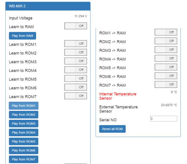
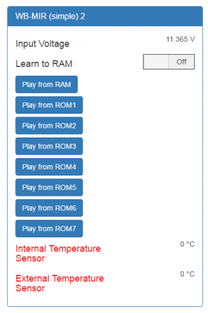
At the moment, to connect the module WB-MIR, there are two templates: WB-MIR and WB-MIR (simple). Template WB-MIR provides a complete set of functions of the module from the web interface, including training, and a simplified version WB-MIR (simple) can be used with the already trained remote control and contains a much smaller number of controls.
On the example of a fully functional module, consider the main controls of the module and their purpose.
| The name of the control | Purpose |
|---|---|
| Input Voltage | module supply Voltage |
| Learn-to-RAM | Write the IR signal in the operational buffer (see section Operational mode). For learning, the control is turned ON, after learning — OFF. |
| Play from RAM | Play the IR signal from the operating buffer (see Operating mode). |
| Learn to ROMx | IR signal Recording ACC. the cell of the ROM (see section DC mode). For learning, the control is turn ON position, after learning — OFF. |
| Play from ROMx | Play IR signal from resp. ROM cells (see Constant mode]). For learning, the control is transferred to THE on position, after learning — OFF. |
| ROMx -> RAM | Copy data from ACC. ROM cells to the online buffer for editing (see Constant mode). For editing, control is transferred to THE on position, after editing — OFF. |
| Internal/External Temperature Sensor | Internal/external digital temperature sensor. If the sensor is missing or defective, its name is highlighted in red. |
| Serial NO | the Serial number of the WB-MIR module may be required when contacting technical support. |
| Reset all ROM | Resets the contents of all memory locations. Be careful, ROM cleaning will be done without asking for confirmation! |
Command-line device management
The Wiren Board controller software includes modbus_client utility to work with devices connected to the RS-485 outputs, via Modbus Protocol, the detailed description of the command is on the page Modbus client. Access to the command line is described in SSH.
Register reading example
Let's check whether it is true that we are connected to the module of the desired type. (Module wb-mqtt-serial needs to be stopped). At address 200, a unique signature of 6 registers is stored. Let's read 6 registers, starting with the address 200, and convert the received answer from hexadecimal digits into a character string:
echo  -e `modbus_client --debug -mrtu -pnone -s2 /dev/ttyAPP1 \
-a1 -t0x03 -r200 -c 6 | \
grep Data | sed -e 's/0x00/\\\x/g' -e 's/Data://' -e 's/\s//g'`
As a result of the command, we receive string WBMIR. The WB-MIR module in the example has Modbus address 1.
