WBE2-I-1-WIRE 1-Wire Extension Module/en: различия между версиями
FuzzyBot (обсуждение | вклад) м (FuzzyBot переименовал страницу Wiren Board 6: Модуль расширения 1-Wire/en в WBE2-I-1-WIRE 1-Wire Extension Module/en без оставления перенаправления: Часть переводимой страницы Wiren Board 6: Модуль расширения 1-Wire.) |
|||
| (не показано 14 промежуточных версий 1 участника) | |||
| Строка 10: | Строка 10: | ||
The signals are output to the O1-O3 terminals of the extension module. | The signals are output to the O1-O3 terminals of the extension module. | ||
Pinout: | |||
{| class="wikitable" | {| class="wikitable" | ||
! | !Terminal | ||
! | !Function | ||
|- | |- | ||
|O1 | |O1 | ||
| Строка 24: | Строка 24: | ||
|GND | |GND | ||
|} | |} | ||
== | == Configuration == | ||
Configuration is set in the web interface under Configs => Hardware Modules Configuration. | |||
In the Internal slot 1 or 2 section (depending on the slot number) select "WBE2-I-1-WIRE" and click Save. | |||
The device is detected immediately, no reboot is required. After adding the device the output of the dmesg command will display a message <code>i2c-gpio mod1_i2c: using pins 24 (SDA) and 25 (SCL)</code> | |||
== | == Operation == | ||
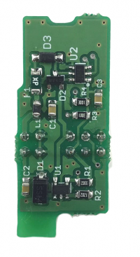
[[ | [[File:1wire.PNG|thumb|400px|1-Wire extension module]] | ||
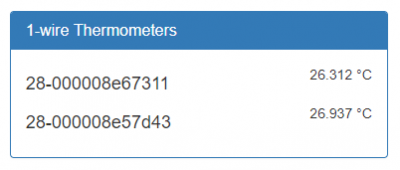
After the sensors are connected to the controller, they appear in the Devices, column 1-wire Thermometers. | |||
== | == Known bugs and features == | ||
=== ERRE21W01: | === ERRE21W01: Unstable operation with long line === | ||
==== | ==== Affected devices ==== | ||
WBE2-I-1-WIRE | WBE2-I-1-WIRE | ||
==== | ====Description==== | ||
See https://support.wirenboard.com/t/problemy-s-wbe2-i-1-wire/2967 (ru) | |||
The WBE2-I-1-WIRE module works worse on long lines than the W1-W2 ports on the Wiren Board 6. | |||
==== | ====Reasons and detailed description==== | ||
Work features of the applied chip DS2484 and protection circuits are the causes. The protection circuit limits the signal fronts when the DS2484 active pullup is active. The DS2484 bus master mistakenly enables an active pullup on a long line at the time of data transfer (active low) by the sensors. | |||
The chip also has a small sampling time, which makes its operation more sensitive to the steepness of the fronts, and therefore to the length of the line. | |||
==== | ====Workarounds==== | ||
Use ports W1, W2 on the Wiren Board 6 when problems occur. | |||
Apply for a warranty replacement for a new version of the module. | |||
==== | ====Scheduled fix=== | ||
No plans. WBE2-I-1WIRE is out of production, the new module WBE2-I-1WIRE-V2 is planned, which does not have this problem. | |||
Текущая версия на 15:23, 22 апреля 2021
Hardware
The module contains GPIO protection, an active 1-Wire line pull-up and a current limiter at 5Vout.
Pinout
The signals are output to the O1-O3 terminals of the extension module.
Pinout:
| Terminal | Function |
|---|---|
| O1 | 5Vout |
| O2 | 1-W |
| O3 | GND |
Configuration
Configuration is set in the web interface under Configs => Hardware Modules Configuration.
In the Internal slot 1 or 2 section (depending on the slot number) select "WBE2-I-1-WIRE" and click Save.
The device is detected immediately, no reboot is required. After adding the device the output of the dmesg command will display a message i2c-gpio mod1_i2c: using pins 24 (SDA) and 25 (SCL)
Operation
After the sensors are connected to the controller, they appear in the Devices, column 1-wire Thermometers.
Known bugs and features
ERRE21W01: Unstable operation with long line
Affected devices
WBE2-I-1-WIRE
Description
See https://support.wirenboard.com/t/problemy-s-wbe2-i-1-wire/2967 (ru)
The WBE2-I-1-WIRE module works worse on long lines than the W1-W2 ports on the Wiren Board 6.
Reasons and detailed description
Work features of the applied chip DS2484 and protection circuits are the causes. The protection circuit limits the signal fronts when the DS2484 active pullup is active. The DS2484 bus master mistakenly enables an active pullup on a long line at the time of data transfer (active low) by the sensors. The chip also has a small sampling time, which makes its operation more sensitive to the steepness of the fronts, and therefore to the length of the line.
Workarounds
Use ports W1, W2 on the Wiren Board 6 when problems occur. Apply for a warranty replacement for a new version of the module.
=Scheduled fix
No plans. WBE2-I-1WIRE is out of production, the new module WBE2-I-1WIRE-V2 is planned, which does not have this problem.

