WBIO-AI-DV-12/4-20mA Analog Inputs/en: различия между версиями
(Новая страница: «'''Unlike other WBIO modules, only one instance can be connected to a single controller or interface module.'''») |
(Новая страница: «To connect, you need to dock the WBIO-AI-DV-12 4-20 mА module to the right of the Wiren Board controller and make sure that all the connector pins on the module…») |
||
| Строка 77: | Строка 77: | ||
'''Unlike other WBIO modules, only one instance can be connected to a single controller or interface module.''' | '''Unlike other WBIO modules, only one instance can be connected to a single controller or interface module.''' | ||
To connect, you need to dock the WBIO-AI-DV-12 4-20 mА module to the right of the Wiren Board controller and make sure that all the connector pins on the module get into the corresponding connector holes on the controller. Next, you should go to the web interface of the controller (read more about the web interface in [[web interface_wiren_board|relevant section]]), go to the tab ''''Configs'''' and select'''''/etc/wb-hardware.conf'''''. Next, in the drop-down list, select the module name '''''WBIO-AI-DV-12 Analog Inputs'''''. | |||
{| class="wikitable" | {| class="wikitable" | ||
Версия 09:30, 16 июля 2019
<languages> Внимание: Отображаемое название «WBIO-AI-DV-12 4-20мА analog inputs module» переопределяет ранее заданное отображаемое название «WBIO-AI-DV-12 4-20MA».
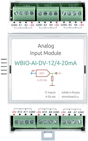
The module is designed for industrial and home automation systems and is used to measure current signals in the range up to 20 mA. A typical application of the module can be considered to receive data from devices that transmit information on the interface "current loop".
IMPORTANT: unlike other WBIO modules, only one instance can be connected to a single controller or interface module.
Buy WBIO-AI-DV-12_4-20MA in the online store
Design
The module contains 12 current inputs A1 — A12 for the connection of current outputs (0) 4 — 20 mA ("current loop").
For easy connection, each pair of inputs is output to one of 6 terminals. In addition to the inputs, each terminal block has +5 V and iGND lines, but the maximum current flowing through the +5 V line should not exceed 0.5 A. Thus, each terminal block has +5 V, 2 current inputs and iGND.
The module is galvanically isolated from the controller circuits, including the iGND line.
Technical specifications
| Parameter | Value |
|---|---|
| General | |
| Number of inputs | 12 |
| Input type | analog, current measurement |
| Galvanic isolation | group, from controller circuits, 1 kV |
| Measured current | 0 — 20 mA |
| Input impedance | 50 Ohms |
| Measurement error | 0.1% + 0.003 mA |
| Other | |
| Module type | "I" (inverted address scheme) |
| Maximum power consumption | 0.25 W |
| Width, DIN units | 3 |
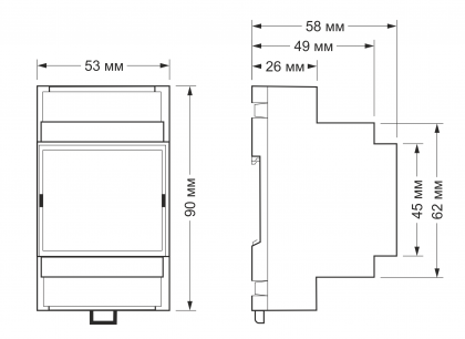
| Overall dimensions (l x W x h) | 53.30 x 90.2 x 57.50 mm |
| Terminals and wire section | |
|---|---|
| The recommended wire cross section with pin bushing insulated tip, mm2 | 0,75 — 1 |
| Standard sleeve length of pin bushing insulated tip, mm | 8 |
| Tightening torque of screws, Н∙м | 0,2 |
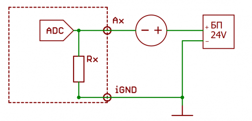
Current measurement
Connection to the controller
Unlike other WBIO modules, only one instance can be connected to a single controller or interface module.
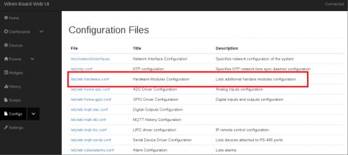
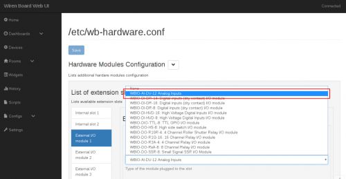
To connect, you need to dock the WBIO-AI-DV-12 4-20 mА module to the right of the Wiren Board controller and make sure that all the connector pins on the module get into the corresponding connector holes on the controller. Next, you should go to the web interface of the controller (read more about the web interface in relevant section), go to the tab 'Configs' and select/etc/wb-hardware.conf. Next, in the drop-down list, select the module name WBIO-AI-DV-12 Analog Inputs.
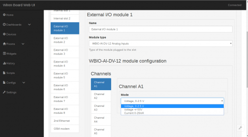
Теперь нужно активировать необходимый режим работы во вкладке "Channels". Каналы обозначаются в виде "Channel Ax", где 'x' соответствует номерe входа. Выберите из списка настройку Current 0-20mA
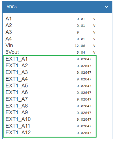
После необходимой настройки и сохранения изменений, устройство отобразится во вкладке "Devices".
Для дополнительной информации смотрите раздел Активация нового модуля в веб-интерфейсе контроллера. Модуль WBIO-AI-DV-12 4-10 мА может подключаться девятым модулем в линейке боковых модулей, в дополнение к обычным восьми. Однако при этом он должен занимать первую, пятую или девятую позицию в линейке модулей.
Изображения и чертежи устройства
По ссылкам ниже вы можете скачать изображения и чертежи устройства WBIO-AI-DV-12_4-20.
Corel Draw 2018: WBIO-AI-DV-12_4-20.cdr.zip
Corel Draw PDF: WBIO-AI-DV-12_4-20.cdr.pdf
Autocad 2013 DXF: Мы еще не подготовили чертеж этого устройства. Вы можете запросить чертеж устройства "Analog inputs module WBIO-AI-DV-12 for measuring analog signals 4-20 мА" на портале техподдержки Wiren Board (необходима регистрация).
Известные ошибки и особенности
ERRAIDV01: Сниженная точность входов
Подверженные устройства
WBIO-AI-DV-12/4-20MA отгруженные до 20 мая 2019г.
Описание
Ошибка измерения тока в WBIO-AI-DV-12/4-20MA может составлять до 1%.
Причины и подробное описание
Номинал входного защитного резистора выбран слишком большим относительно внутренного сопротивления АЦП.
Пути обхода
нет
Запланированное исправление
Начиная с 20 мая 2019г. в WBIO-AI-DV-12/4-20MA устанавливаются компоненты, обеспечивающие ошибку не более 0.1%+0.003мА.
