WBIO-AI-DV-12/4-20mA Analog Inputs/en: различия между версиями
(Новая страница: «The module is designed for industrial and home automation systems and is used to measure current signals in the range up to 20 mA. A typical application of the mo…») |
FuzzyBot (обсуждение | вклад) м (FuzzyBot переименовал страницу WBIO-AI-DV-12 Analog Inputs 4-20mA/en в WBIO-AI-DV-12/4-20mA Analog Inputs/en без оставления перенаправления: Часть переводимой страницы WBIO-AI-DV-12 Analog Inputs 4-20mA.) |
||
| (не показаны 44 промежуточные версии 2 участников) | |||
| Строка 5: | Строка 5: | ||
The module is designed for industrial and home automation systems and is used to measure current signals in the range up to 20 mA. A typical application of the module can be considered to receive data from devices that transmit information on the interface [https://en.wikipedia.org/wiki/Current_loop "current loop"]. | The module is designed for industrial and home automation systems and is used to measure current signals in the range up to 20 mA. A typical application of the module can be considered to receive data from devices that transmit information on the interface [https://en.wikipedia.org/wiki/Current_loop "current loop"]. | ||
''' | '''IMPORTANT: unlike other WBIO modules, only one instance can be connected to a single controller or interface module.''' | ||
'''[https://wirenboard.com/ru/product/WBIO-AI-DV-12_4-20MA/ | '''[https://wirenboard.com/ru/product/WBIO-AI-DV-12_4-20MA/ Buy WBIO-AI-DV-12_4-20MA in the online store ]''' | ||
== | ==Design== | ||
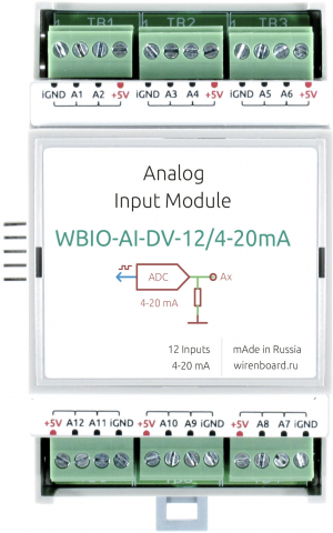
The module contains 12 current inputs A1 — A12 for the connection of current outputs (0) 4 — 20 mA ([https://en.wikipedia.org/wiki/Current_loop "current loop"]). | |||
For easy connection, each pair of inputs is output to one of 6 terminals. In addition to the inputs, each terminal block has +5 V and iGND lines, but the maximum current flowing through the +5 V line should not exceed 0.5 A. Thus, each terminal block has +5 V, 2 current inputs and iGND. | |||
The module is galvanically isolated from the controller circuits, including the iGND line. | |||
== | ==Technical specifications== | ||
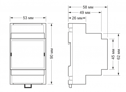
[[ | [[File:DIN 3U.png|mini|420x600px|overall dimensions]] | ||
{| class="wikitable" | {| class="wikitable" | ||
! | !Parameter | ||
! | !Value | ||
|- | |- | ||
! colspan="2" | | ! colspan="2" |General | ||
|- | |- | ||
| | |Number of inputs | ||
|12 | |12 | ||
|- | |- | ||
| | |Input type | ||
| | |analog, current measurement | ||
|- | |- | ||
| | |Galvanic isolation | ||
| | |group, from controller circuits, 1 kV | ||
|- | |- | ||
| | |Measured current | ||
|0 — 20 | |0 — 20 mA | ||
|- | |- | ||
| | |Input impedance | ||
|50 | |50 Ohms | ||
|- | |- | ||
| | |Measurement error | ||
|0.1% + 0.003 | |0.1% + 0.003 mA | ||
|- | |- | ||
! colspan="2" | | ! colspan="2" |Other | ||
|- | |- | ||
| | |Module type | ||
|"I" (inverted address scheme) | |"I" (inverted address scheme) | ||
|- | |- | ||
| | |Maximum power consumption | ||
|0 | |0.25 W | ||
|- | |- | ||
| | |Width, DIN units | ||
|3 | |3 | ||
|- | |- | ||
| | |Overall dimensions (l x W x h) | ||
|53 | |53.30 x 90.2 x 57.50 mm | ||
|} | |} | ||
{| class="wikitable" | {| class="wikitable" | ||
!colspan="2" | ''' | !colspan="2" | '''Terminals and wire section''' | ||
|- | |- | ||
|| | || The recommended wire cross section with pin bushing insulated tip, mm<sup>2</sup> || 0,75 — 1 | ||
|- | |- | ||
|| | || Standard sleeve length of pin bushing insulated tip, mm || 8 | ||
|- | |- | ||
|| | ||Tightening torque of screws, Н∙м || 0,2 | ||
|- | |- | ||
|} | |} | ||
== | == Current measurement == | ||
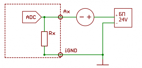
[[ | [[File:Current_Sensor.png|500px|thumb|left|Current sensor connection]] | ||
== | == Connection to the controller == | ||
'''Unlike other WBIO modules, only one instance can be connected to a single controller or interface module.''' | |||
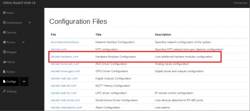
To connect, you need to dock the WBIO-AI-DV-12 4-20 mА module to the right of the Wiren Board controller and make sure that all the connector pins on the module get into the corresponding connector holes on the controller. Next, you should go to the web interface of the controller (read more about the web interface in [[web interface_wiren_board|relevant section]]), go to the tab ''''Configs'''' and select'''''/etc/wb-hardware.conf'''''. Next, in the drop-down list, select the module name '''''WBIO-AI-DV-12 Analog Inputs'''''. | |||
{| class="wikitable" | {| class="wikitable" | ||
| [[ | | [[File:DV12WebInterface.jpg|500px|thumb|center|Desired configuration file]] | ||
| [[ | | [[File:DV12WebInterface2.jpg|500px|thumb|center|Module selection]] | ||
|} | |} | ||
Now you need to activate the desired mode in the tab '''''Channels'''''. Channels are denoted as '''''Channel Ax''''', where 'x' corresponds to the entry number. | |||
Select from the list the setting '''Current 0-20mA''' | |||
After the necessary settings and saving changes, the device will be displayed in the '''''Devices'''''tab. | |||
{| class="wikitable" | {| class="wikitable" | ||
| [[ | | [[File:Dv12Web4.png|500px|thumb|center|login mode settings]] | ||
| [[ | | [[File:WEB-WBIO-AI-DV-12_4-20MA.png|500px|thumb|center|Display inputs with different operating modes]] | ||
|} | |} | ||
For more information, see [[Модули ввода-вывода/en#Activating the modules in the controller web interface|Activating the modules in the web interface of the controller]]. | |||
Unlike other modules, WBIO-AI-DV-12 can be connected with the ninth module in the line of side modules. However, it must occupy '''the first, fifth or ninth position''' in the line. | |||
<!-- == | <!-- == Connection via WB-MIO interface converter == | ||
Unlike other WBIO modules, only one instance can be connected to a single controller or interface module. | |||
[[ | [[File:Scale_WBIO_AI_DV_12.png|500px|thumb|right|the value of the '''scale''' factor of the dimensions is chosen equal to 0.2126 for measuring voltage of ±50 V]] | ||
[[ | [[File:AI-DV-12_VIA_WB_MIO.png|300px|thumb|left|View of the WBIO-AI-DV-12 module connected via the WB-MIO converter in the controller web interface]] | ||
The WBIO-AI-DV-12 module can also be connected via the interface converter [[WB-MIO/en|WB-MIO]]. Two device templates can be used: WBIO-AI-DV-12-50V and WBIO-AI-DV-12. If they are not in the configurator, you need to update wb-mqtt-serial with <code>apt-get update && apt-get install wb-mqtt-serial</code>. The WBIO-AI-DV-12-50V template is designed for devices where jumpers are installed (voltage measurement on differential inputs in the range from 0 to 50 V), and the WBIO-AI-DV-12 template is for devices with removed jumpers (voltage measurement on differential inputs from 0 to 400 mV, on unipolar inputs — from 0 to 2.5 V). | |||
''' | '''Warning, the information below is outdated and will be deleted!''' | ||
Previously, when connecting the module via WB-MIO or WB-MIO-E, there was no possibility to select the input mode from the web interface. We recommended creating copies of the config-wbio-ai-dv-12-single template.json stored on the controller in the <code>/usr/share/wb-mqtt-serial/templates/config-wbio-ai-dv-12-single directory.json </code>, and make changes to the copy (the file must have a different name). It was necessary to change the device type in the template, for example, to <code>"device_type": "WBIO-AI-DV-12-Single-50v",</code>. After that, you had to restart the wb-mqtt-confed service and refresh the web page to make the new device type available in the configuration. | |||
For each channel, you can specify a conversion factor (scale) corresponding to the measurement mode. Restartujte service wb-mqtt-serial after changes: | |||
<code>> service wb-mqtt-serial restart<br>> service wb-mqtt-confed restart</code> | <code>> service wb-mqtt-serial restart<br>> service wb-mqtt-confed restart</code> | ||
The most correct way is to set the measurement scale parameter in the channel setup in the device configuration. Let's say we want to measure the voltage in the ±50 V range at the first differential input. | |||
To do this, perform the following settings. In the device properties, add a channel list (List if channels) by clicking on the '''Properties''' button, and then add a channel by clicking on the '''+Item''' button. | |||
In the channel settings, we leave only the field for specifying the conversion factor (Scale (value multiplier)), the other options are disabled: | |||
Specify the channel name (as in the interface) and conversion factor. | |||
Save changes with the '''Save''' button at the top of the screen. | |||
<br /> | <br /> | ||
| Строка 123: | Строка 123: | ||
{| class="wikitable" style="text-align:center" | {| class="wikitable" style="text-align:center" | ||
|[[ | |[[File:Ai-dv-12-add_list_of_channels.png|400px|thumb|right|Add channel list]] | ||
|[[ | |[[File:Ai-dv-12-only-scale.png|400px|thumb|left|Leave only the scale]] | ||
|[[ | |[[File:Ai-dv-12-DIFF1_right_scale.png|600px|thumb|right|Set the channel name and conversion factor]] | ||
|} | |} | ||
| Строка 131: | Строка 131: | ||
{| class="wikitable" style="text-align:center" | {| class="wikitable" style="text-align:center" | ||
|+ | |+ Dependence of the input operation mode on the installed jumper and scaling factor | ||
!''' | !'''The presence of the jumper'''!! '''Entry type'''!! '''Mode''' || '''Value scale''' | ||
|- | |- | ||
|rowspan="2"|''' | |rowspan="2"|'''No''' | ||
| | |Unipolar | ||
| | |Input voltage 0 — 2.5 V | ||
|0.01 | |0.01 | ||
|- | |- | ||
| | |Differential | ||
| | |Input voltage ±400 mV | ||
|0.01 | |0.01 | ||
|- | |- | ||
|rowspan="2"|''' | |rowspan="2"|'''Is''' | ||
|- | |- | ||
| | |Differential | ||
| | |Input voltage ±50 V | ||
|0.2126 | |0.2126 | ||
|} | |} | ||
For models designed to measure current, the '''scale' ''factor must be set to 0.1 | |||
-- | -- | ||
== | ==Device pictures and drawings == | ||
{{Wbincludes:WBPicturesNoDrawing|2}} | {{Wbincludes:WBPicturesNoDrawing|2}} | ||
== | == Bugs and features == | ||
=== ERRAIDV01: | === ERRAIDV01: Reduced precision of inputs === | ||
==== | ==== Affected devices ==== | ||
WBIO-AI-DV-12/4-20MA | WBIO-AI-DV-12/4-20MA shipped before May 20, 2019. | ||
==== | ====Description==== | ||
Current measurement error in WBIO-AI-DV-12/4-20MA can be up to 1%. | |||
==== | ====Reasons and detailed description==== | ||
The nominal value of the input protective resistor is selected too large relative to the internal resistance of the ADC. | |||
==== | ====Workarounds==== | ||
no | |||
==== | ====Scheduled fix=== | ||
Starting from May 20,2019 components, providing the error is not more than 0.1%+0.003 mA, are installed in WBIO-AI-DV-12/4-20MA | |||
Текущая версия на 14:19, 22 апреля 2021
<languages> Внимание: Отображаемое название «WBIO-AI-DV-12 4-20мА analog inputs module» переопределяет ранее заданное отображаемое название «WBIO-AI-DV-12 4-20MA».
The module is designed for industrial and home automation systems and is used to measure current signals in the range up to 20 mA. A typical application of the module can be considered to receive data from devices that transmit information on the interface "current loop".
IMPORTANT: unlike other WBIO modules, only one instance can be connected to a single controller or interface module.
Buy WBIO-AI-DV-12_4-20MA in the online store
Design
The module contains 12 current inputs A1 — A12 for the connection of current outputs (0) 4 — 20 mA ("current loop").
For easy connection, each pair of inputs is output to one of 6 terminals. In addition to the inputs, each terminal block has +5 V and iGND lines, but the maximum current flowing through the +5 V line should not exceed 0.5 A. Thus, each terminal block has +5 V, 2 current inputs and iGND.
The module is galvanically isolated from the controller circuits, including the iGND line.
Technical specifications
| Parameter | Value |
|---|---|
| General | |
| Number of inputs | 12 |
| Input type | analog, current measurement |
| Galvanic isolation | group, from controller circuits, 1 kV |
| Measured current | 0 — 20 mA |
| Input impedance | 50 Ohms |
| Measurement error | 0.1% + 0.003 mA |
| Other | |
| Module type | "I" (inverted address scheme) |
| Maximum power consumption | 0.25 W |
| Width, DIN units | 3 |
| Overall dimensions (l x W x h) | 53.30 x 90.2 x 57.50 mm |
| Terminals and wire section | |
|---|---|
| The recommended wire cross section with pin bushing insulated tip, mm2 | 0,75 — 1 |
| Standard sleeve length of pin bushing insulated tip, mm | 8 |
| Tightening torque of screws, Н∙м | 0,2 |
Current measurement
Connection to the controller
Unlike other WBIO modules, only one instance can be connected to a single controller or interface module.
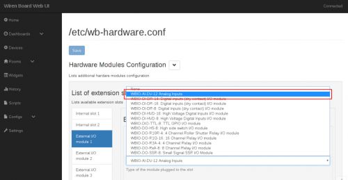
To connect, you need to dock the WBIO-AI-DV-12 4-20 mА module to the right of the Wiren Board controller and make sure that all the connector pins on the module get into the corresponding connector holes on the controller. Next, you should go to the web interface of the controller (read more about the web interface in relevant section), go to the tab 'Configs' and select/etc/wb-hardware.conf. Next, in the drop-down list, select the module name WBIO-AI-DV-12 Analog Inputs.
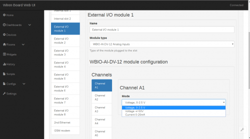
Now you need to activate the desired mode in the tab Channels. Channels are denoted as Channel Ax, where 'x' corresponds to the entry number. Select from the list the setting Current 0-20mA
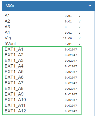
After the necessary settings and saving changes, the device will be displayed in the Devicestab.
For more information, see Activating the modules in the web interface of the controller. Unlike other modules, WBIO-AI-DV-12 can be connected with the ninth module in the line of side modules. However, it must occupy the first, fifth or ninth position in the line.
