WBIO-AI-DV-12 I/O Module
The module is designed for industrial and home automation systems and is used to measure the values of analog signals. Typical applications of the module can be considered as receiving data with analog thermometers or measurement of the stresses for each element batteries.
IMPORTANT: unlike other WBIO modules, only one instance can be connected to a single controller or interface module.
Buy WBIO-AI-DV-12 in the online store
Buy WBIO-AI-DV-12_4-20MA in the online store
For a description of the current input module WBIO-AI-DV-12_4-20 mA, see separate page.
Design
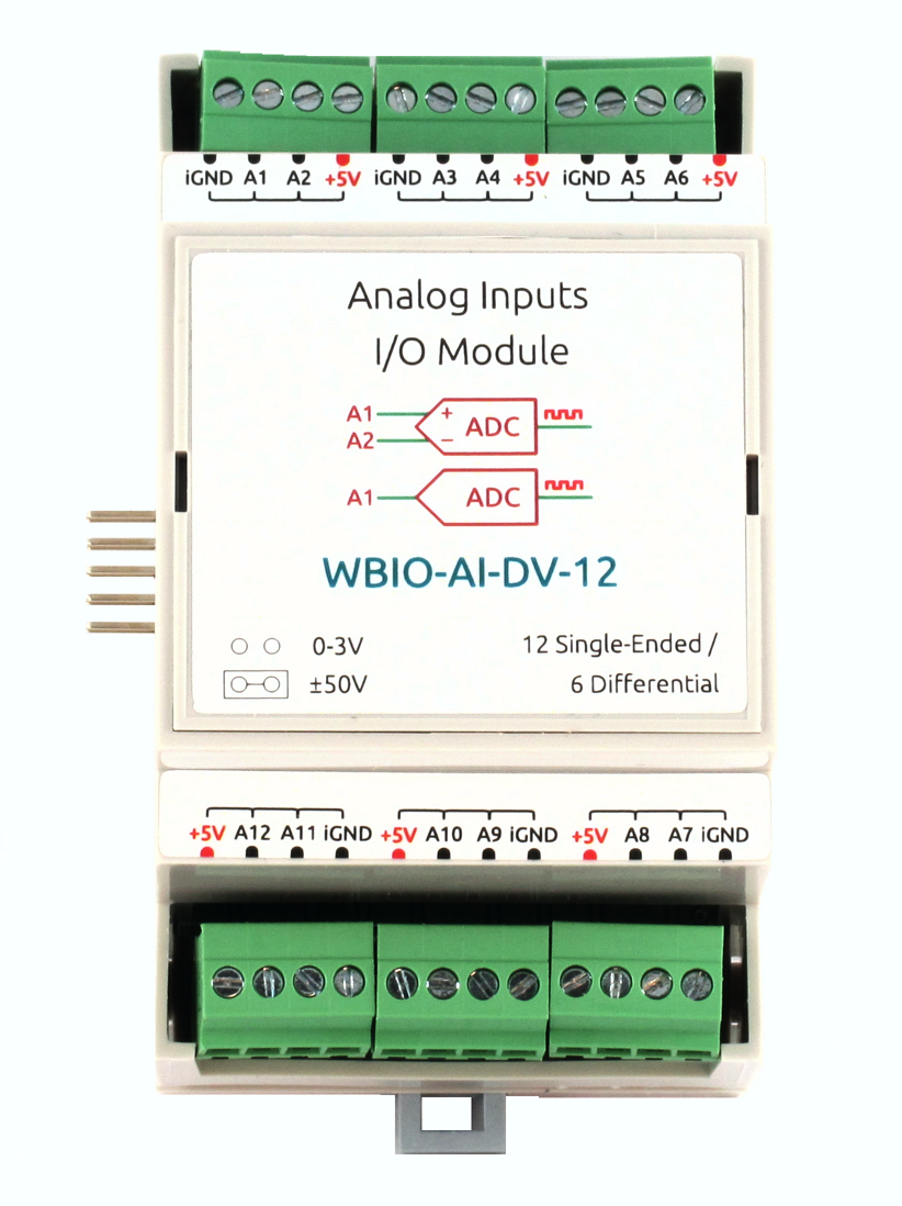
The module contains 12 universal analog inputs combined into 6 pairs of differential inputs. In unipolar mode, the voltage is measured relative to the iGND line.
Each of the six pairs can be configured to work as:
- 2 unipolar voltage inputs 0 — 2.5 V
- 1 differential voltage input ±400 mV
- 1 ±50 V differential voltage input
For easy connection, each pair of inputs is output to one of 6 terminals. In addition to the inputs, each terminal block has +5 V and iGND lines, but the maximum current flowing through the +5 V line must not exceed 0.5 A. Thus, each terminal block has: +5 V, 2 analog inputs and iGND.
The measurement modes are set by means of jumpers inside the module body. The module is galvanically isolated from the controller circuits, including iGND line.
Technical specifications
| Parameter | Value |
|---|---|
| General | |
| Number of inputs | 12 (unipolar) |
| 6 (differential) | |
| Input type | voltage measurement |
| Galvanic isolation | group, from controller circuits, 1 kV |
| ±50 V Mode | |
| Measured voltage | -50 To ... +50 Volts |
| Allowable voltage | -100 Volts ... +100 V DC |
| Input impedance | 50 kω |
| 0-2,5 V Mode | |
| Measured voltage | 0...2.5 Volts |
| Allowable voltage | -50 To ... +50 V DC |
| Input impedance | >3 MOhm |
| Input impedance | 50 Ohms |
| Other | |
| Inaccuracy of measurements | 1% |
| Module type | "I" (inverted address scheme) |
| Maximum power consumption | 0.25 W |
| Width, DIN units | 3 |
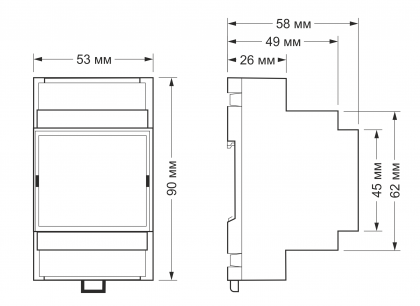
| Overall dimensions (l x W x h) | 53.30 x 90.2 x 57.50 mm |
| Terminals and wire section | |
|---|---|
| The recommended wire cross section with pin bushing insulated tip, mm2 | 0,75 — 1 |
| Standard sleeve length of pin bushing insulated tip, mm | 8 |
| Tightening torque of screws, Н∙м | 0,2 |
The setting of the operation modes
This module has several modes of operation (they are described in the table below). Changing the operating mode is carried out by installing jumpers inside the device.
| The presence of the jumper | Operating mode |
|---|---|
| No | Unipolar input voltage 0 — 2.5 V |
| Differential voltage input ±400 mV | |
| Is | |
| Differential voltage input ±50 V |
0 — 2.5 V unipolar voltage input
To set the input to this mode, you must set the appropriate setting in the web interface of the controller (for details, see connection section). The jumper on the contact group related to this input, is not set.
Differential voltage input is ±400 mV
The principle of operation of the differential input is to compare the two values and output the difference between them as readings. Accordingly, to activate this mode, it is necessary to use two adjacent inputs: inputs 1 and 2; 3 and 4; 5 and 6, etc. in this Case, both jumpers on the contact groups related to the involved differential inputs, are not installed, and in the web interface of the controller for these inputs should be set to Voltage, 0-2.5 V'.
Differential voltage input is ±50 V
This mode also uses two adjacent analog inputs. You should to install jumpers to the contacts pertaining to both inputs. In the web interface of the controller,select the "Voltage, +- 50V" mode for both inputs (for details, see connection section).
In this mode, the voltage difference applied to the corresponding analog inputs will be measured.
Installing jumpers
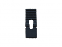
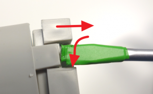
Installation of jumpers is carried out on the contact groups related to the corresponding inputs. To do this, remove the top cover of the device by pulling it through special holes with a flat screwdriver. Remove and install jumpers can be, for example, tweezers. If, due to any circumstances, the installation of jumpers through the removed top cover is difficult, it is necessary to disassemble the device, observing the following procedure:
- Remove the terminals.
- Remove the back cover of the device by bending 4 latches in turn around the perimeter. It is necessary to unbend latches a flat subject (for example, a screwdriver), without making thus big efforts and at the same time disconnecting the case and a back cover.
- Release the board from the top of the case. To do this, you need to release the device from all connected terminals, and then slightly bend the body in the place indicated in the figure and release the edge of the Board. The remaining edge of the Board (with protruding contacts) will be released without difficulty.
- Having installed the necessary jumpers, the device is assembled in the reverse order (i.e. from the institution to the body of the edge of the Board with protruding contacts).
Файл:DV12 Razor.png Module with removed cover |
Файл:DV12 Plata's Peremuchkami.png Installing jumpers | |
Each input has its own contact group (pin connectors on the board). Contact groups are located opposite the terminal block of the corresponding input and are marked with a sticker on the body, signed on the Board itself and shown in the figure. In the figure given as an example, you can see that the jumpers are installed on inputs 2 and 3 at the moment.
Connection to the controller
Unlike other WBIO modules, only one instance can be connected to a single controller or interface module.
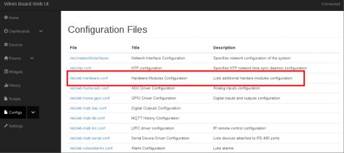
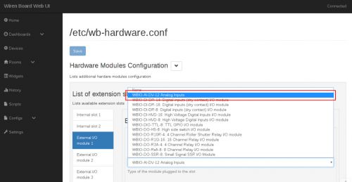
To connect, you need to dock the WBIO-AI-DV-12 module to the right of the WIren Board controller, making sure that all the connector pins on the module get into the corresponding connector holes on the controller. Next, you should go to the web interface of the controller (read more about the web interface in relevant section), go to the tab 'Configs' and select/etc/wb-hardware.conf. Next, in the drop-down list, select the module name WBIO-AI-DV-12 Analog Inputs.
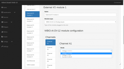
Now you can activate the desired mode in the Channels tab. Channels are denoted as Channel Ax, where 'x' corresponds to the entry number. To activate the desired mode of operation of the input, you must select the following settings:
- 0 — 2.5 V single-pole voltage input or ±400 mV differential voltage input
- Voltage, 0-2.5 V
- ±50 V single-pole or differential voltage input
- Voltage +/-50V
Note: to activate the differential mode of the inputs, you need to set the appropriate setting on the of both inputs.
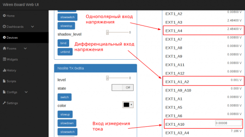
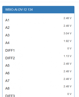
After the necessary settings and saving changes, the device will be displayed in the Devicestab.
Для дополнительной информации смотрите раздел Активация нового модуля в веб-интерфейсе контроллера. В отличие от других модулей, WBIO-AI-DV-12 может подключаться девятым модулем в линейке боковых модулей. Однако при этом он должен занимать первую, пятую или девятую позицию в линейке.
Подключение через преобразователь интерфейсов WB-MIO
В отличие от других WBIO модулей, может быть подключен только один экземпляр к одному контроллеру или интерфейсному модулю.
Модуль WBIO-AI-DV-12 можно подключать и через преобразователь интерфейсов WB-MIO. При этом могут использоваться два шаблона устройства: WBIO-AI-DV-12-50V и WBIO-AI-DV-12. Если их нет в конфигураторе, вам необходимо обновить wb-mqtt-serial командой apt-get update && apt-get install wb-mqtt-serial. Шаблон WBIO-AI-DV-12-50V предназначен для устройств, где перемычки-джамперы установлены (измерение напряжения на дифференциальных входах в диапазоне от 0 до 50 В), а шаблон WBIO-AI-DV-12 — для устройств со снятыми перемычками (измерение напряжений на дифференциальных входах от 0 до 400 мВ, на однополярых — от 0 до 2,5 В).
Внимание, информация ниже устарела и будет удалена!
Ранее при подключении модуля через WB-MIO или WB-MIO-E отсутсвовала возможность выбора режима входов из web-интерфейса. Мы рекомендовали создать копии шаблона config-wbio-ai-dv-12-single.json, хранящийся на контроллере в директории /usr/share/wb-mqtt-serial/templates/config-wbio-ai-dv-12-single.json , и внести изменения в копию (файл должен иметь другое имя). При этом необходимо было изменить в шаблоне тип устройства, например на "device_type": "WBIO-AI-DV-12-Single-50v",. После этого было необходимо перезапустить службу wb-mqtt-confed и обновить веб страницу, чтобы новый тип устройства стал доступен в конфигурации.
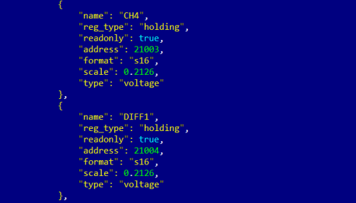
Для каждого канала можно указывать свой коэффициента пересчета (масштаб), соответствующий режиму измерения. Рестартуйте сервис wb-mqtt-serial после внесения изменений:
> service wb-mqtt-serial restart
Наиболее правильным способом является установка параметра масштаба измерений в настройке каналов в конфигурации устройства. Допустим, мы хотим измерять на первом дифференциальном входе напряжение в дианазоне ±50 В.
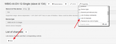
Для этого выполняем следующие настройки. В свойствах устройства добавляем список каналов (List if channels), щелкнув на кнопке Properties, а затем добавляем канал, щелкнув на кнопке +Item.
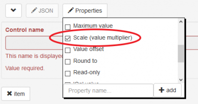
В настройках канала оставляем только поле для указания коэффициента пересчета (Scale (value multiplier)), остальные опции отключаем:
Указываем имя канала (как в интерфейсе) и коэффициент пересчета.
Сохраняем изменения кнопкой Save вверху экрана.
> service wb-mqtt-confed restart
| Наличие перемычки | Тип входа | Режим работы | Значение scale |
|---|---|---|---|
| Нет | Однополярный | Вход напряжения 0 — 2,5 В | 0.01 |
| Дифференциальный | Вход напряжения ±400 мВ | 0.01 | |
| Есть | |||
| Дифференциальный | Вход напряжения ±50 В | 0.2126 |
Изображения и чертежи устройства
По ссылкам ниже вы можете скачать изображения и чертежи устройства WBIO-AI-DV-12.
Corel Draw 2018: WBIO-AI-DV-12.cdr.zip
Corel Draw PDF: WBIO-AI-DV-12.cdr.pdf
Autocad 2013 DXF: Мы еще не подготовили чертеж этого устройства. Вы можете запросить чертеж устройства "analog WBIO-AI-DV-12" на портале техподдержки Wiren Board (необходима регистрация).
