WBIO-DI-DR-16 I/O Module/en: различия между версиями
(Новая страница: «Such devices form a signal by closing two wires that are suitable for them. Connect one wire to the GND terminal of the module. Connect the second wire to the Dx…») |
(Новая страница: «'''Devices with open collector output.'''») |
||
| Строка 82: | Строка 82: | ||
Such devices form a signal by closing two wires that are suitable for them. Connect one wire to the GND terminal of the module. Connect the second wire to the Dx terminal. A current of less than 2 mA flows through the button. Some counters have a pulse output on the optocoupler, then the two wires have a polarity - "plus" and "minus". In this case, minus is connected to GND, plus to Dx. | Such devices form a signal by closing two wires that are suitable for them. Connect one wire to the GND terminal of the module. Connect the second wire to the Dx terminal. A current of less than 2 mA flows through the button. Some counters have a pulse output on the optocoupler, then the two wires have a polarity - "plus" and "minus". In this case, minus is connected to GND, plus to Dx. | ||
''' | '''Devices with open collector output.''' | ||
Устройство и модуль должны иметь общую землю. Выход "открытый коллектор" подключите к клемме Dx. | Устройство и модуль должны иметь общую землю. Выход "открытый коллектор" подключите к клемме Dx. | ||
Версия 17:23, 3 июля 2019
This model is discontinued. Recommended replacement is WBIO-DI-WD-14 Buy WBIO-DI-WD-14 online
Purpose
Connection of pulse counters, buttons, switches, sensors with dry contact output.
Technical specifications
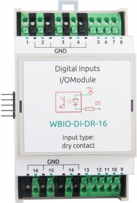
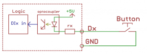
It contains 16 inputs for connection of dry contacts, united in two groups of 8 inputs with group galvanic isolation. The scheme of inputs is shown in the figure. The terminal is supplied with a voltage of 4.5 — 5.5 V, a small current flows to the ground (1-2 mA), causing the operation of the input.
| Parameter | Value |
|---|---|
| Number of inputs | 16 |
| Isolated input groups | 2 |
| Input type | dry contact,
the opening by the current at earth fault |
| Operation condition | GND input lockout |
| Tripping current | 1 mA |
| Minimum pulse width to trigger | 10 MS |
| Minimum time between consecutive signals | 5 MS |
| Voltage "wetting" | 4.5 V |
| Module type | "I" (inverted address scheme) |
| Maximum power consumption | 0.2 W |
| Width, DIN units | 3 |
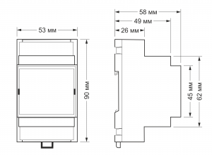
| Size | 53,3x90,2x57,5 mm |
| Terminals and wire section | |
|---|---|
| Recommended wire cross-section with TSVI, mm2 | 0,75 — 1 |
| Length of the standard sleeve NSVE, mm | 8 (10 for adjusting screwless terminal blocks) |
| Torque of screws, N∙m | 0,2 (for screw terminals) |
Connection to controller
See section activating the module in the web interface of the controller. controls like EXTx_DR(1-16) appear in Discrete I/O device, corresponding to the inputs of the module. Corresponding MQTT topics (read-only) look like: /devices/wb-gpio/controls/EXTx_DRy.
Connectivity
Sensors/counters with pulse outputs/buttons.
Such devices form a signal by closing two wires that are suitable for them. Connect one wire to the GND terminal of the module. Connect the second wire to the Dx terminal. A current of less than 2 mA flows through the button. Some counters have a pulse output on the optocoupler, then the two wires have a polarity - "plus" and "minus". In this case, minus is connected to GND, plus to Dx.
Devices with open collector output.
Устройство и модуль должны иметь общую землю. Выход "открытый коллектор" подключите к клемме Dx.
Входы модуля гальванически развязаны от контроллера. Поэтому земли GND модуля и контроллера могут быть разными.
Обратите внимание, что для подключения устройств ко входам 1 — 8 используются клеммники GND верхнего ряда, а для входов 9 — 16 — нижнего.
Изображения и чертежи устройства
По ссылкам ниже вы можете скачать изображения и чертежи устройства WBIO-DI-DR-16.
Corel Draw 2018: WBIO-DI-DR-16.cdr.zip
Corel Draw PDF: WBIO-DI-DR-16.cdr.pdf
Autocad 2013 DXF: WBIO-DI-DR-16.dxf.zip
Autocad PDF: WBIO-DI-DR-16.pdf


