WBIO-DO-R10A-8 Relay Module/en: различия между версиями
(Новая страница: «==Technical specifications==») |
(Новая страница: «== Images and drawings of the device == {{WBPictures|1}}») |
||
| (не показано 13 промежуточных версий этого же участника) | |||
| Строка 10: | Строка 10: | ||
==Technical specifications== | ==Technical specifications== | ||
Contains 8 HF32F-G relays ([http://www.hongfa.com/pro/pdf/HF32F-G_en.pdf Datasheet]) with SPST contacts configuration (two contacts per relay: NO/COM) switching the corresponding 8 outputs. The outputs are output to screw clamps designed for a maximum current of 20 A. | |||
Permissible current up to 7A per channel. The module has protection against sparking of the contacts. | |||
Our detailed article in russian on habr.com about the choice of relay parameters for the switched load: https://habr.com/ru/company/wirenboard/blog/422197/ | |||
{| class="wikitable" | {| class="wikitable" | ||
! | !Parameter | ||
! | !Value | ||
|- | |- | ||
| | |Number of outputs | ||
|8 | |8 | ||
|- | |- | ||
| | |Output type | ||
| | |mechanical relay | ||
|- | |- | ||
| | |Contact configuration | ||
|SPST, | |SPST, normally open | ||
states: | |||
* | * off. | ||
* | * C is closed and NO | ||
|- | |- | ||
| | |Maximum switching voltage, alternating current | ||
|250 | |250 V | ||
|- | |- | ||
| | |Maximum switching voltage, direct current | ||
|30 | |30 Volts | ||
|- | |- | ||
| | |Maximum switching current, per channel (*) | ||
|7 | |7 A | ||
|- | |- | ||
| | |The channel resistance in the open state | ||
|< 100 | |< 100 megohms | ||
|- | |- | ||
| | |Voltage isolation between the controller and the output | ||
|1500 | |1500 V (RMS.) | ||
|- | |- | ||
| | |Lifetime: number of switches | ||
for load 10 A 230 V AC, cos φ = 1 | |||
|100 000 | |100 000 | ||
|- | |- | ||
| | |Module type | ||
|"O" (non-inverted address scheme) | |"O" (non-inverted address scheme) | ||
|- | |- | ||
| | |Maximum power consumption | ||
|1 | |1 W | ||
|- | |- | ||
| | |Width, DIN units | ||
|3 | |3 | ||
|- | |- | ||
| | |Size | ||
|53,3x90,2x57,5 | |53,3x90,2x57,5 mm | ||
|} | |} | ||
<nowiki>*</nowiki>) | <nowiki>*</nowiki>) Maximum switching current is specified for 230 VAC resistive load. | ||
{| class="wikitable" | {| class="wikitable" | ||
!colspan="2" | ''' | !colspan="2" | '''Terminals and wire section''' | ||
|- | |- | ||
|| | || The recommended wire cross section with pin bushing insulated tip, mm<sup>2</sup> || 2,5 | ||
|- | |- | ||
|| | || Standard sleeve length of pin bushing insulated tip, mm || 8 | ||
|- | |- | ||
|| | ||Tightening torque of screws, Н∙м || 0,5 | ||
|- | |- | ||
|} | |} | ||
[[File:DIN 3U.png |300px|thumb|right| | [[File:DIN 3U.png |300px|thumb|right|Dimensions]] | ||
== | == Connection to the controller == | ||
See [[Модули ввода-вывода/en#Activating the modules in the controller web interface|Activating the modules in the web interface of the controller]]. In the Module type field, select '''WBIO-DO-RxA-8: 8 Channel Relay I/O module'''. In the web interface the relay will be presented by the controls of EXT'''x'''_R3A1 — EXT'''x'''_R3A8 of the Discrete I/O devices. The corresponding MQTT-topics: /devices/wb-gpio/controls/EXT'''x'''_R3A'''y'''. | |||
[[File:Wbio-do-rxa-8_controls.png|300px|thumb|right| | [[File:Wbio-do-rxa-8_controls.png|300px|thumb|right|Controls of the module in the web interface]] | ||
== | == Load connection== | ||
Relays are connected in a phase break. | |||
[[Файл:Relay outputs.png|400px|thumb|none| | [[Файл:Relay outputs.png|400px|thumb|none|Connection scheme]] | ||
== | == Images and drawings of the device == | ||
{{Wbincludes:WBPictures|1}} | {{Wbincludes:WBPictures|1}} | ||
Текущая версия на 17:27, 15 июля 2019
Purpose
Control of lighting, motors, contactors.
Technical specifications
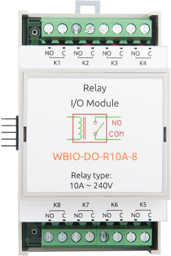
Contains 8 HF32F-G relays (Datasheet) with SPST contacts configuration (two contacts per relay: NO/COM) switching the corresponding 8 outputs. The outputs are output to screw clamps designed for a maximum current of 20 A.
Permissible current up to 7A per channel. The module has protection against sparking of the contacts.
Our detailed article in russian on habr.com about the choice of relay parameters for the switched load: https://habr.com/ru/company/wirenboard/blog/422197/
| Parameter | Value |
|---|---|
| Number of outputs | 8 |
| Output type | mechanical relay |
| Contact configuration | SPST, normally open
states:
|
| Maximum switching voltage, alternating current | 250 V |
| Maximum switching voltage, direct current | 30 Volts |
| Maximum switching current, per channel (*) | 7 A |
| The channel resistance in the open state | < 100 megohms |
| Voltage isolation between the controller and the output | 1500 V (RMS.) |
| Lifetime: number of switches
for load 10 A 230 V AC, cos φ = 1 |
100 000 |
| Module type | "O" (non-inverted address scheme) |
| Maximum power consumption | 1 W |
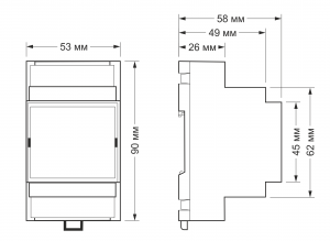
| Width, DIN units | 3 |
| Size | 53,3x90,2x57,5 mm |
*) Maximum switching current is specified for 230 VAC resistive load.
| Terminals and wire section | |
|---|---|
| The recommended wire cross section with pin bushing insulated tip, mm2 | 2,5 |
| Standard sleeve length of pin bushing insulated tip, mm | 8 |
| Tightening torque of screws, Н∙м | 0,5 |
Connection to the controller
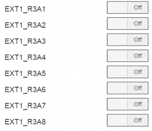
See Activating the modules in the web interface of the controller. In the Module type field, select WBIO-DO-RxA-8: 8 Channel Relay I/O module. In the web interface the relay will be presented by the controls of EXTx_R3A1 — EXTx_R3A8 of the Discrete I/O devices. The corresponding MQTT-topics: /devices/wb-gpio/controls/EXTx_R3Ay.
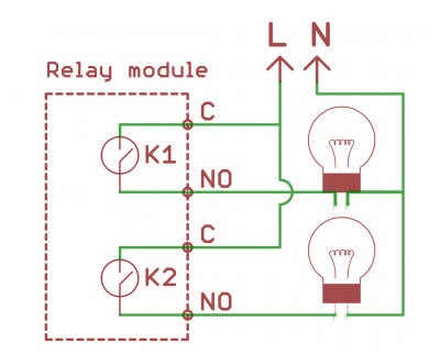
Load connection
Relays are connected in a phase break.
Images and drawings of the device
По ссылкам ниже вы можете скачать изображения и чертежи устройства WBIO-AO-10V-8.
Corel Draw 2018: WBIO-AO-10V-8.cdr.zip
Corel Draw PDF: WBIO-AO-10V-8.cdr.pdf
Autocad 2013 DXF: WBIO-AO-10V-8.dxf.zip
Autocad PDF: WBIO-AO-10V-8.pdf


