Wellpro/en: различия между версиями
(Новая страница: « Wellpro devices») |
FuzzyBot (обсуждение | вклад) м (FuzzyBot переименовал страницу Устройства Wellpro/en в Wellpro/en без оставления перенаправления: Часть переводимой страницы Устройства Wellpro.) |
||
| (не показано 35 промежуточных версий 2 участников) | |||
| Строка 1: | Строка 1: | ||
</ | <languages/> | ||
== | ==Technical parameters== | ||
Wellpro Adam series devices support Modbus RTU Protocol over RS-485 bus. The devices are mounted on a 35 mm DIN rail or screwed on top of the same device or a Wellpro device with a similar housing design. | |||
===Коммуникационные параметры по умолчанию=== | ===Коммуникационные параметры по умолчанию=== | ||
| Строка 10: | Строка 10: | ||
* Скорость — 9600 бит/с | * Скорость — 9600 бит/с | ||
=== | ===Default communication settings=== | ||
*The bit depth is 8 | |||
*Stop bit — 1 | |||
*Parity check — no | |||
*Speed — 9600 bps | |||
===Modbus registers=== | |||
The address is written to '''0x64''' register ,address 0x00 with a single device on the bus. | |||
Register '''0x65''' stores communication parameters. After recording, you may need to restart. | |||
{| class="wikitable" | {| class="wikitable" | ||
! | !Value | ||
! | !Speed | ||
! | !Parameters | ||
|- | |- | ||
|0x0001 | |0x0001 | ||
| Строка 52: | Строка 58: | ||
|} | |} | ||
=== | ===Power/Data status light=== | ||
The Power/Data status light is green when power is supplied,it is blinking when data is received and sent, or it is red when an error occurs or when another device is accessed on the bus. | |||
==Wellpro WP3066ADAM== | ==Wellpro WP3066ADAM== | ||
The Wellpro WP3066ADAM is a data acquisition module for DS18B20 temperature sensors. Up to 8 sensors can be connected to the module. | |||
[[Файл:3066.png|thumb | 200px| Wellpro WP3066ADAM]] | [[Файл:3066.png|thumb | 200px| Wellpro WP3066ADAM]] | ||
=== | ==Technical specifications== | ||
*Operating temperature— -20-70°C | |||
*Power — external DC power supply 9V — 30V | |||
*Power consumption — 2 W | |||
===Pin assignment=== | |||
* | *AVcc — "+" power supply module | ||
* | *AGnd — "-" module power | ||
* | *485A — line A RS485 (+) | ||
*485B — line A RS485 (+) | |||
*Vdd — +5V for power supply to DS18B20 sensor | |||
*Gnd — DS18B20 sensor ground | |||
*Data'''1-8''' — sensor data output 1 — 8 DS18B20 | |||
=== | ===Modbus Registers=== | ||
Storage registers (Holding registers) 0x00-0x07 contain temperature information received from the sensor. A 0xFFFF value read from the register means that the sensor is not connected. | |||
The temperature is determined as follows: | |||
*DATA > 10000 — temperature below 0°C, TEMP =-(DATA-10000)/10 | |||
* DATA > 10000 — | *DATA < 10000, the measured temperature exceeds 0°C, TEMP = DATA/10 | ||
* DATA < 10000, | |||
''' | ''' Negative temperature values are not supported by the current version of the Wirenboard template!''' | ||
==Wellpro WP9038ADAM== | ==Wellpro WP9038ADAM== | ||
The WP9038ADAM I / o module has 4 digital inputs, 4 digital outputs and 6 analog inputs. | |||
[[Файл:9038.png|thumb | 200px| Wellpro WP9038ADAM]] | [[Файл:9038.png|thumb | 200px| Wellpro WP9038ADAM]] | ||
=== | ===Technical parameters=== | ||
* | *Analog inputs — 0-20 ± 2 mA DC | ||
* | *Digital inputs — active level low | ||
* | *Digital outputs — NPN-open collector transistor output, 500mA | ||
* | *Operating temperature— -20-70°C | ||
* | *Power supply — 9-30 V DC | ||
* | *Power consumption — 2 W | ||
=== | ===Pin assignment=== | ||
* AVcc — "+" | *AVcc — "+" power supply module | ||
* AGnd — "-" | *AGnd — "-" module power | ||
* | *485A — line A RS485 (+) | ||
* 485B — | *485B — line A RS485 (+) | ||
* | *DI_1-4 — digital inputs | ||
* | *DO_1-4 — digital outputs | ||
* | *AI_1-6+ — positive analog inputs | ||
* Gnd | *Gnd is the signal ground for analog inputs. | ||
The analog outputs allow three — wire sensors to be connected- in this case the sensor is connected to the Gnd and the sensor power supply - " + " sensor to the sensor power supply "+" and the signal wire to the AI_x+terminal. When two-wire connection Gnd is connected to the "-" of the power source sensor, and the sensor is connected to the "+" power source of the sensor and the output AI_x+ | |||
The digital outputs are protected by a diode and allow switching of relays or indicators connected to the DO_x and "+" pin of the main power supply. | |||
The digital inputs are galvanically isolated via the optocoupler; a button or switch is connected to the DIx pin and the "-" main power supply of the module. | |||
=== | ===Modbus registers=== | ||
* | *Holding registers 0x00-0x05 contain the values of the analog signal being read. The current in milliamperes is calculated by the formula I = (DATA*20)/4095. | ||
* | *Discrete input registers (Discrete Input registers) 0x00-0x03 allow you to read the status of digital di inputs. | ||
* | *Registers flags (Coil registers) 0x00-0x03 enable write/read status of digital outputs DO. | ||
=== | ===Power/Data status light=== | ||
The Power/Data status light is green when power is supplied,it is blinking when data is received and sent, or it is red when an error occurs or when another device is accessed on the bus. | |||
The red lights DI 1-4 (four to the left) indicate the presence of a logical 1 at the corresponding digital input and DO 1-4 (four | |||
to the right) lights - at the corresponding digital output. | |||
==Wellpro WP8028ADAM== | ==Wellpro WP8028ADAM== | ||
The WP8028ADAM I/O module has 8 digital inputs and 8 digital outputs. | |||
[[Файл:8028.png|thumb | 200px| Wellpro WP8028ADAM]] | [[Файл:8028.png|thumb | 200px| Wellpro WP8028ADAM]] | ||
=== | ===Technical parameters=== | ||
* | *Digital inputs — active level low | ||
* | *Digital outputs — NPN-open collector transistor output, 500mA | ||
* | *Operating temperature— -20-70°C | ||
* | *Power supply — 9-30 V DC | ||
* | *Power consumption — 2 W | ||
===Pin assignment=== | |||
*AVcc — "+" power supply module | |||
*AGnd — "-" module power | |||
*485A — line A RS485 (+) | |||
*485B — line A RS485 (+) | |||
*DI_0'''1-8''' — digital inputs | |||
*DO_0'''1-8''' — digital outputs | |||
The digital outputs are protected by a diode and allow switching relays or indicators connected to the DO and "+" pin of the main power supply. | |||
The digital inputs are galvanically isolated via the optocoupler; a button or switch is connected to the DIx pin and to the "-" of the main power supply of the module. | |||
=== | ===Modbus Registers=== | ||
* | *Discrete Input registers '''0x00-0x07''' allow you to read the state of digital inputs. | ||
* | *Coil registers '''0x00-0x07''' allow you to record/read the status of digital outputs. | ||
=== | ===Power/Data status light=== | ||
The Power/Data status light is green when power is supplied,it is blinking when data is received and sent, or it is red when an error occurs or when another device is accessed on the bus. | |||
Red indicators DO 1-8 indicate the presence of a logical 1 on the corresponding digital output, and DI 1-8 — on the corresponding digital input. | |||
Текущая версия на 21:28, 1 июля 2021
Technical parameters
Wellpro Adam series devices support Modbus RTU Protocol over RS-485 bus. The devices are mounted on a 35 mm DIN rail or screwed on top of the same device or a Wellpro device with a similar housing design.
Коммуникационные параметры по умолчанию
- Разрядность — 8 бит
- Стоп-бит — 1
- Проверка четности — нет
- Скорость — 9600 бит/с
Default communication settings
- The bit depth is 8
- Stop bit — 1
- Parity check — no
- Speed — 9600 bps
Modbus registers
The address is written to 0x64 register ,address 0x00 with a single device on the bus.
Register 0x65 stores communication parameters. After recording, you may need to restart.
| Value | Speed | Parameters |
|---|---|---|
| 0x0001 | 4800 | 8N1 |
| 0x0002 | 9600 | 8N1 |
| 0x0003 | 19200 | 8N1 |
| 0x0004 | 38400 | 8N1 |
| 0x0005 | 4800 | 8E1 |
| 0x0006 | 9600 | 8E1 |
| 0x0007 | 19200 | 8E1 |
| 0x0008 | 38400 | 8E1 |
Power/Data status light
The Power/Data status light is green when power is supplied,it is blinking when data is received and sent, or it is red when an error occurs or when another device is accessed on the bus.
Wellpro WP3066ADAM
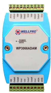
The Wellpro WP3066ADAM is a data acquisition module for DS18B20 temperature sensors. Up to 8 sensors can be connected to the module.
Technical specifications
- Operating temperature— -20-70°C
- Power — external DC power supply 9V — 30V
- Power consumption — 2 W
Pin assignment
- AVcc — "+" power supply module
- AGnd — "-" module power
- 485A — line A RS485 (+)
- 485B — line A RS485 (+)
- Vdd — +5V for power supply to DS18B20 sensor
- Gnd — DS18B20 sensor ground
- Data1-8 — sensor data output 1 — 8 DS18B20
Modbus Registers
Storage registers (Holding registers) 0x00-0x07 contain temperature information received from the sensor. A 0xFFFF value read from the register means that the sensor is not connected.
The temperature is determined as follows:
- DATA > 10000 — temperature below 0°C, TEMP =-(DATA-10000)/10
- DATA < 10000, the measured temperature exceeds 0°C, TEMP = DATA/10
Negative temperature values are not supported by the current version of the Wirenboard template!
Wellpro WP9038ADAM
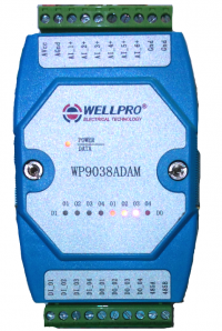
The WP9038ADAM I / o module has 4 digital inputs, 4 digital outputs and 6 analog inputs.
Technical parameters
- Analog inputs — 0-20 ± 2 mA DC
- Digital inputs — active level low
- Digital outputs — NPN-open collector transistor output, 500mA
- Operating temperature— -20-70°C
- Power supply — 9-30 V DC
- Power consumption — 2 W
Pin assignment
- AVcc — "+" power supply module
- AGnd — "-" module power
- 485A — line A RS485 (+)
- 485B — line A RS485 (+)
- DI_1-4 — digital inputs
- DO_1-4 — digital outputs
- AI_1-6+ — positive analog inputs
- Gnd is the signal ground for analog inputs.
The analog outputs allow three — wire sensors to be connected- in this case the sensor is connected to the Gnd and the sensor power supply - " + " sensor to the sensor power supply "+" and the signal wire to the AI_x+terminal. When two-wire connection Gnd is connected to the "-" of the power source sensor, and the sensor is connected to the "+" power source of the sensor and the output AI_x+
The digital outputs are protected by a diode and allow switching of relays or indicators connected to the DO_x and "+" pin of the main power supply.
The digital inputs are galvanically isolated via the optocoupler; a button or switch is connected to the DIx pin and the "-" main power supply of the module.
Modbus registers
- Holding registers 0x00-0x05 contain the values of the analog signal being read. The current in milliamperes is calculated by the formula I = (DATA*20)/4095.
- Discrete input registers (Discrete Input registers) 0x00-0x03 allow you to read the status of digital di inputs.
- Registers flags (Coil registers) 0x00-0x03 enable write/read status of digital outputs DO.
Power/Data status light
The Power/Data status light is green when power is supplied,it is blinking when data is received and sent, or it is red when an error occurs or when another device is accessed on the bus.
The red lights DI 1-4 (four to the left) indicate the presence of a logical 1 at the corresponding digital input and DO 1-4 (four
to the right) lights - at the corresponding digital output.
Wellpro WP8028ADAM
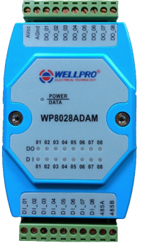
The WP8028ADAM I/O module has 8 digital inputs and 8 digital outputs.
Technical parameters
- Digital inputs — active level low
- Digital outputs — NPN-open collector transistor output, 500mA
- Operating temperature— -20-70°C
- Power supply — 9-30 V DC
- Power consumption — 2 W
Pin assignment
- AVcc — "+" power supply module
- AGnd — "-" module power
- 485A — line A RS485 (+)
- 485B — line A RS485 (+)
- DI_01-8 — digital inputs
- DO_01-8 — digital outputs
The digital outputs are protected by a diode and allow switching relays or indicators connected to the DO and "+" pin of the main power supply.
The digital inputs are galvanically isolated via the optocoupler; a button or switch is connected to the DIx pin and to the "-" of the main power supply of the module.
Modbus Registers
- Discrete Input registers 0x00-0x07 allow you to read the state of digital inputs.
- Coil registers 0x00-0x07 allow you to record/read the status of digital outputs.
Power/Data status light
The Power/Data status light is green when power is supplied,it is blinking when data is received and sent, or it is red when an error occurs or when another device is accessed on the bus.
Red indicators DO 1-8 indicate the presence of a logical 1 on the corresponding digital output, and DI 1-8 — on the corresponding digital input.


