Wiren Board: Extension Modules/en: различия между версиями
FuzzyBot (обсуждение | вклад) м (FuzzyBot переименовал страницу Wiren Board 6: Extension Modules/en в Wiren Board: Extension Modules/en без оставления перенаправления: Часть переводимой страницы Wiren Board 6: Extension Modules.) |
|||
| (не показано 9 промежуточных версий 1 участника) | |||
| Строка 21: | Строка 21: | ||
|- | |- | ||
|WBE2-I-RS232 | |WBE2-I-RS232 | ||
|[[ | |[[Wiren_Board_6:_Модуль_расширения_RS-232_(WBE2-I-RS232)/en| RS-232 Extension module]] | ||
|RS-232 | |RS-232 | ||
|1 | |1 | ||
| Строка 27: | Строка 27: | ||
|- | |- | ||
|WBE2-I-CAN-ISO | |WBE2-I-CAN-ISO | ||
|[[ | |[[Wiren_Board_6:_Модуль_расширения_CAN_(WBE2-I-CAN-ISO)/en| CAN-ISO extension module]] | ||
|CAN, UART-CAN | |CAN, UART-CAN | ||
|1 | |1 | ||
| Строка 33: | Строка 33: | ||
|- | |- | ||
|WBE2-I-RS485-ISO | |WBE2-I-RS485-ISO | ||
|[[ | |[[Wiren_Board_6:_Модуль_расширения_RS485-ISO_(WBE2-I-RS485-ISO)/en| RS-485-ISO extension module]] | ||
|RS-485 | |RS-485 | ||
|1 | |1 | ||
| Строка 39: | Строка 39: | ||
|- | |- | ||
|WBE2-I-1-WIRE | |WBE2-I-1-WIRE | ||
|[[ | |[[Wiren_Board_6:_Модуль_расширения_1-Wire/en|1-Wire extension module]] | ||
|1-Wire | |1-Wire | ||
|1 | |1 | ||
| Строка 45: | Строка 45: | ||
|- | |- | ||
|WBE2-I-KNX | |WBE2-I-KNX | ||
|[[ | |[[KNX_Module_for_WB6_(WBE2-I-KNX)/en| KNX extension module]] | ||
|KNX | |KNX | ||
|1 | |1 | ||
| Строка 53: | Строка 53: | ||
|- | |- | ||
|WBE2-DI-DR-3 | |WBE2-DI-DR-3 | ||
|[[Wiren_Board_6: | |[[Wiren_Board_6:_Модуль_расширения_"сухие_контакты"_(WBE2-DI-DR-3)/en|Dry contact extension module]] | ||
|dry contact | |dry contact | ||
|3 | |3 | ||
| Строка 62: | Строка 62: | ||
|WBE2-DO-R6C-1 | |WBE2-DO-R6C-1 | ||
|[[Wiren_Board_6: | |[[Wiren_Board_6:_Модуль_релейных_выходов_(WBE2-DO-R6C-1)/en|Relay outputs module]] | ||
|relay | |relay | ||
|1 | |1 | ||
| Строка 68: | Строка 68: | ||
|- | |- | ||
|WBE2-DO-SSR-2 | |WBE2-DO-SSR-2 | ||
|[[Wiren_Board_6:_Модуль_выходов_"сухой_контакт"_(оптореле) | |[[Wiren_Board_6:_Модуль_выходов_"сухой_контакт"_(оптореле)_(WBE2-DO-SSR-2)/en|Solid state relay module]] | ||
|solid state relay | |solid state relay | ||
|2 | |2 | ||
| Строка 74: | Строка 74: | ||
|- | |- | ||
|WBE2-DO-OC-2 | |WBE2-DO-OC-2 | ||
|[[Wiren_Board_6:_Модуль_выходов_"Открытый_коллектор" | |[[Wiren_Board_6:_Модуль_выходов_"Открытый_коллектор"_(WBE2-DO-OC-2)/en|Open collector outputs module]] | ||
|open collector | |open collector | ||
|2 | |2 | ||
| Строка 82: | Строка 82: | ||
|- | |- | ||
|WBE2-AO-10V-2 | |WBE2-AO-10V-2 | ||
|[[Служебная:MyLanguage/Wiren Board 6: Модуль расширения DAC (WBE2-AO-10V-2)| Dual-channel module with 0-10V DAC analog outputs]] — 2 voltage outputs (0 — 10 V) | |[[Служебная:MyLanguage/Wiren Board 6: Модуль расширения DAC (WBE2-AO-10V-2)/en| Dual-channel module with 0-10V DAC analog outputs]] — 2 voltage outputs (0 — 10 V) | ||
|analog outputs | |analog outputs | ||
|2 | |2 | ||
| Строка 90: | Строка 90: | ||
|- | |- | ||
|WBE2S-MICROSD | |WBE2S-MICROSD | ||
|[[Служебная:MyLanguage/Wiren_Board_6:_WBE2S-MICROSD_Extension_Module| microSD extension module]] | |[[Служебная:MyLanguage/Wiren_Board_6:_WBE2S-MICROSD_Extension_Module/en| microSD extension module]] | ||
| | | | ||
| | | | ||
| Строка 96: | Строка 96: | ||
|- | |- | ||
|WBE2R-R-GPS | |WBE2R-R-GPS | ||
|[[ | |[[Wiren_Board_6:_WBE2R-R-GPS_GPS/GLONASS_Extension_Module/en| GPS/Glonass extension module]] | ||
| | | | ||
| | | | ||
| Строка 108: | Строка 108: | ||
|- | |- | ||
|WBE2S-R-433MHZ | |WBE2S-R-433MHZ | ||
|[[ | |[[Wiren_Board_6:_Модуль_расширения_433MHz_(WBE2S-R-433MHZ)/en| 433MHz extension module]] | ||
| | | | ||
| | | | ||
| Строка 130: | Строка 130: | ||
==Module and connector compatibility== | ==Module and connector compatibility== | ||
The Wiren Board 6 has three connectors for extension modules of two different types: | The Wiren Board 6 has three connectors for extension modules of two different types: | ||
| Строка 166: | Строка 165: | ||
#Insert the module, observing polarity, the tab on the module should fit into the slot on the controller board. | #Insert the module, observing polarity, the tab on the module should fit into the slot on the controller board. | ||
Each module description contains the detailed information for installation.The description is given in the [[# | Each module description contains the detailed information for installation.The description is given in the [[#List|List of extension modules]] table. | ||
==Configuration== | ==Configuration== | ||
After the physical connection, you need to configure it in the controller interface. To do this, go to the '''Hardware Modules Configuration''' section of the web interface, select one of the three extension slots (Internal slot 1, 2 or 3) and select the type of the installed module from the '''Module type''' dropdown list. Click '''Save''': the module is installed and ready to use. To remove a module, select '''None'''. Click '''Save'''. | After the physical connection, you need to configure it in the controller interface. To do this, go to the '''Hardware Modules Configuration''' section of the web interface, select one of the three extension slots (Internal slot 1, 2 or 3) and select the type of the installed module from the '''Module type''' dropdown list. Click '''Save''': the module is installed and ready to use. To remove a module, select '''None'''. Click '''Save'''. | ||
Текущая версия на 14:32, 5 февраля 2024
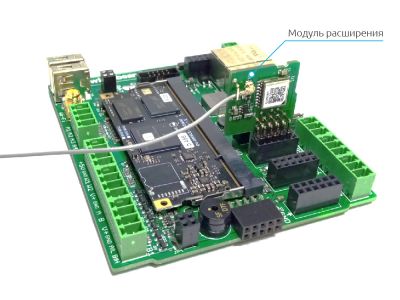
Extension modules are small electronic boards installed inside the Wiren Board 6 to extend its functionality.
List
| Article | Description | Interface | Number
channels' |
Insulation |
|---|---|---|---|---|
| interfaces | ||||
| WBE2-I-RS232 | RS-232 Extension module | RS-232 | 1 | no |
| WBE2-I-CAN-ISO | CAN-ISO extension module | CAN, UART-CAN | 1 | 1.5 kV |
| WBE2-I-RS485-ISO | RS-485-ISO extension module | RS-485 | 1 | 1.5 kV |
| WBE2-I-1-WIRE | 1-Wire extension module | 1-Wire | 1 | no |
| WBE2-I-KNX | KNX extension module | KNX | 1 | no |
| discrete inputs | ||||
| WBE2-DI-DR-3 | Dry contact extension module | dry contact | 3 | no |
| discrete outputs | ||||
| WBE2-DO-R6C-1 | Relay outputs module | relay | 1 | 3 kV |
| WBE2-DO-SSR-2 | Solid state relay module | solid state relay | 2 | no |
| WBE2-DO-OC-2 | Open collector outputs module | open collector | 2 | no |
| analog input-output | ||||
| WBE2-AO-10V-2 | Dual-channel module with 0-10V DAC analog outputs — 2 voltage outputs (0 — 10 V) | analog outputs | 2 | no |
| other | ||||
| WBE2S-MICROSD | microSD extension module | |||
| WBE2R-R-GPS | GPS/Glonass extension module | |||
| WBE2R-R-ZIGBEE | ZigBee extension module | |||
| WBE2S-R-433MHZ | 433MHz extension module | |||
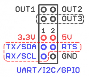
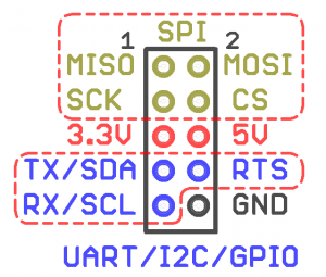
Specification for internal extension connectors
The pinout is shown in the pictures on the right.
Voltages and permissible current:
Power supply:
3.3 V-0.5 A
5 V-0.5 A
Data lines: 3.3 V-10 mA
Module and connector compatibility
The Wiren Board 6 has three connectors for extension modules of two different types:
- MOD1 and MOD2 connectors
- MOD 3 connector
Some extension modules can be installed only in a certain type of connector, some — in all connectors. The compatibility table is shown below:
| Prefix | MOD1 | MOD2 | MOD3 |
|---|---|---|---|
| WBE2- | + | - | |
| WBE2S- | - | + | |
| WBE2R- | + | + | |
For example, WBE2S-MICROSD can be installed only in slot MOD3, and WBE2R-R-GPS — in any slot.
Installation
When ordering modules with the Wiren Board 6controller, these modules come pre-installed by the manufacturer.
If the modules were purchased separately and you are installing them yourself, you need to:
- Remove the bottom cover of the controller enclosure.
- Remove the main board
- Insert the module, observing polarity, the tab on the module should fit into the slot on the controller board.
Each module description contains the detailed information for installation.The description is given in the List of extension modules table.
Configuration
After the physical connection, you need to configure it in the controller interface. To do this, go to the Hardware Modules Configuration section of the web interface, select one of the three extension slots (Internal slot 1, 2 or 3) and select the type of the installed module from the Module type dropdown list. Click Save: the module is installed and ready to use. To remove a module, select None. Click Save.


