Wiren Board 5:Hardware
Multifunctional inputs/outputs A1-A4
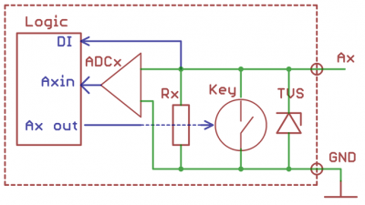
Universal channels consist of parallel operating input and output stage, as well as protective diodes (connected to one channel terminal).
The output stage consists of a switching element Tx. The Tx key closes the outputs to the ground. Under control of logic circuits controller, the Tx switch can be in one of 2 states:
- Active (closed) at the channel output 0.
- Inactive (open, high impedance).
This type of output is called "open collector".
The open collector outputs on the Ax channel are displayed in software as Ax_OUT. The path of the channel is: "wb-gpio/Ax_OUT".
For Ax Channels, the input stage consists of an adcx analog-to-digital Converter and an Rx input impedance (100kω) . The ADCx Converter has a high input impedance, it is connected continuously and is not affected the work of the channel is in output mode. In input mode, the Tx key is put into an Inactive state (open) and therefore not affects the voltage measurement at the channel terminal. The input impedance of the channel in the input mode is determined by the RX resistor: if no other circuits are connected to the channel terminal, the resistor "attract" input voltage 0 power supply and Converter ADCx will assume a voltage equal to 0. The analog inputs on the channels are displayed in Ax as a Ax section of the ADC. Channel address: "wb-adc/Ax".
Also for channels Ah there is a function of binary input DI - the voltage at the terminal more than 3V controller perceives as a logical unit (input operation), less than 1.5 V - as a logical zero. The binary inputs on the Ax channel displayed in software as Ax_IN. The address of the binary input channel is "wb-gpio/Ax_IN".
R1 and R2 Resistive Inputs
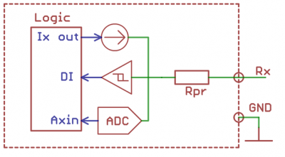
In the default mode, each terminal is connected to an internal regulated current source. The controller supplies a given current to the input, and measures the voltage on it. From the known current and voltage values, THE controller software calculates the resistance connected to the input.
Each input also can be translated in the normal mode of the analog input in the settings. In this mode, the current source is disabled and the input measures voltage in the range 0-3.0 Vol.
R1-R2 inputs also work as binary inputs.
When the current source is turned on (the default mode), the input is pulled to the power supply. If nothing is connected to the input, this state is perceived as a logical unit. If you connect the terminal strip to the ground, it corresponds to a logical zero. External buttons, sensors, etc. in this mode, you need to connect between the RX and GND terminals.
In alternative mode, when the current source is off, the input is pulled to the ground. The logical zero corresponds to the input to which nothing is connected; the logical unit is the input to which the voltage > 3V IS applied. External buttons, sensors, etc. in this mode, you need to connect between the RX terminal strip and the 5V out terminal strip, or the power plus.
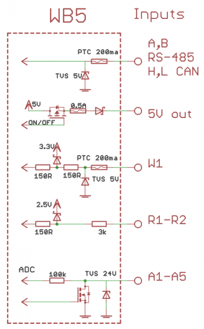
1-Wire and +5V output
1-Wire bus is used for external sensors. The bus utilizes either two or three conductors. The bus allows to connect multiple devices to a single 1-Wire port in parallel.
It is convenient to use +5V output to power the sensors.
It is protected from short circuit and high voltage supply. When the controller is powered by a battery, the +5V output remains active. There is also a software control of this output (it can be disabled).
Подробнее смотрите 1-Wire.
Питание
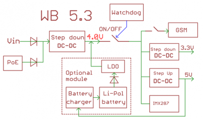
Wiren Board 5 имеет три внешних входа для подключения блоков питания: DC jack, клеммники и Passive PoE. Возможно одновременное подключения источников к разным входам, в том числе с разным напряжением. Подробнее:
- От внешнего блока питания.
Допустимый диапазон питания 7-28В. Среднее потребление платы - 1,5-2 Вт. Но т.к. модуль GSM потребляет импульсно до 8 Вт, рекомендуется использовать блоки питания с мощностью не менее 10 Вт.
Разъем питания под стандартный jack 5.5x2.1мм, также входное напряжение можно подключать к клеммам Vin и GND. В аппаратной ревизии 5.8 и выше блок клемм питания содержит две клеммы Vin, к которым можно подключить два независимых блока питания для резервирования. Земли блоков питания должны быть соединены и подключены к клемме GND.
- Power over Ethernet
Поддерживается питание по кабелю Ethernet. Подробнее смотрите Power over Ethernet.
- Аккумулятор.
Wiren Board позволяет подключить внутренний модуль резервного питания WBMZ-BATTERY с Li-Ion (Li-Pol) аккумулятором.


