Wiren Board 6.7: Peripherals/en: различия между версиями
Matveevrj (обсуждение | вклад) (Новая страница: «== UART implementation ==») |
Matveevrj (обсуждение | вклад) |
||
| (не показана 21 промежуточная версия этого же участника) | |||
| Строка 2: | Строка 2: | ||
{{DISPLAYTITLE:Wiren Board 6.7-6.9.1: Low-level hardware handling}} | {{DISPLAYTITLE:Wiren Board 6.7-6.9.1: Low-level hardware handling}} | ||
{{Wbincludes:Peripherals}} | {{Wbincludes:Peripherals}} | ||
== GPIO terminals == | == GPIO terminals == | ||
{| class="wikitable" | {| class="wikitable" | ||
! | !Terminal block | ||
! | !Function | ||
!GPIO | !GPIO | ||
!GPIO number | !GPIO number | ||
! | !Output i.mx6UL | ||
!Comments | |||
|- | |- | ||
| colspan="6" style="text-align:center; vertical-align: middle; "| | | colspan="6" style="text-align:center; vertical-align:middle;" | '''Outputs A1-A4''' | ||
|- | |- | ||
|A1(out) | |A1(out) | ||
| Строка 42: | Строка 43: | ||
| Open collector output; | | Open collector output; | ||
|- | |- | ||
| colspan="6" style="text-align:center; vertical-align: middle; "| | | colspan="6" style="text-align:center; vertical-align:middle;" | '''Outputs A1-A4''' (inverted; those. "1" on gpio appears when there is no voltage at the input) | ||
|- | |- | ||
|A1 (in) | |A1 (in) | ||
| Строка 91: | Строка 92: | ||
== UART implementation == | == UART implementation == | ||
{| class="wikitable" | {| class="wikitable" | ||
|''' | |'''Port Name in Linux''' | ||
|''' | |'''Alternate Port Name on Linux''' | ||
|''' | |'''Connector on controller''' | ||
|''' | |'''Note''' | ||
|- | |- | ||
|/dev/ttymxc0 | |/dev/ttymxc0 | ||
|/dev/ttyCONSOLE | |/dev/ttyCONSOLE | ||
| | | Controller debug-uart (micro-usb) | ||
| | | Default Settings: 115200-8-N-1 | ||
|- | |- | ||
|/dev/ttymxc1 | |/dev/ttymxc1 | ||
|/dev/ttyRS485-1 | |/dev/ttyRS485-1 | ||
| | | Signed ''RS-485'', terminal blocks A and B | ||
| | | Uninsulated port, terminator installed | ||
|- | |- | ||
|/dev/ttymxc3 | |/dev/ttymxc3 | ||
|/dev/ttyRS485-2 | |/dev/ttyRS485-2 | ||
| | | Signed ''RS-485'', terminal blocks A/L and B/H (this port can be used as CAN) | ||
| | | Uninsulated port, terminator installed, multiplexed with CAN | ||
|- | |- | ||
|/dev/ttymxc2 | |/dev/ttymxc2 | ||
|/dev/ttyMOD1 | |/dev/ttyMOD1 | ||
|UART | | UART on the extension module MOD1 | ||
| | | To appear, you need to set in wb-hardware.conf «Expose UART Pins (DIY)» | ||
|- | |- | ||
|/dev/ttymxc4 | |/dev/ttymxc4 | ||
|/dev/ttyMOD2 | |/dev/ttyMOD2 | ||
|UART | | UART on the extension module MOD2 | ||
| | | To appear, you need to set in wb-hardware.conf «Expose UART Pins (DIY)» | ||
|- | |- | ||
|/dev/ttymxc5 | |/dev/ttymxc5 | ||
|/dev/ttyMOD3 | |/dev/ttyMOD3 | ||
|UART | | UART on the extension module MOD3 | ||
| | | To appear, you need to set in wb-hardware.conf «Expose UART Pins (DIY)» | ||
|- | |- | ||
|/dev/ttymxc6 | |/dev/ttymxc6 | ||
|/dev/ttyMOD4 | |/dev/ttyMOD4 | ||
|UART | | UART on the extension module MOD4 | ||
| | | To appear, you need to set in wb-hardware.conf «Expose UART Pins (DIY)» | ||
|- | |- | ||
|/dev/ttymxc7 | |/dev/ttymxc7 | ||
|/dev/ttyGSM | |/dev/ttyGSM | ||
|UART | | UART on WBC expansion module (GSM/3G/4G modem connector) | ||
| | | To appear, you need to set any of the modems in wb-hardware.conf | ||
|- | |- | ||
|} | |} | ||
<gallery> | <gallery> | ||
File: MOD12.png | Connector Mod1, Mod2 and Mod3 WB6.7 for expansion modules | |||
File: MOD3.png | Connector Mod4 WB6.7 for extension modules | |||
File: wbc_mod.png | Slot WBC connector on the WB6.7 for 2g/3g/4g modems | |||
</gallery> | </gallery> | ||
== Signals on expansion modules == | |||
= | |||
{| class="wikitable" | {| class="wikitable" | ||
|style="text-align:center; vertical-align:middle;" | | |style="text-align:center; vertical-align:middle;" |'''Output sodim''' | ||
|style="text-align:center; vertical-align:middle;" |GPIO | |style="text-align:center; vertical-align:middle;" |'''GPIO''' | ||
|style="text-align:center; vertical-align:middle;" |GPIO number | |style="text-align:center; vertical-align:middle;" |'''GPIO number''' | ||
|style="text-align:center; vertical-align:middle;" | | |style="text-align:center; vertical-align:middle;" |'''Pinmux pad name''' | ||
|style="text-align:center; vertical-align:middle;" | | |style="text-align:center; vertical-align:middle;" |'''Pin''' | ||
|style="text-align:center; vertical-align:middle;" | | |style="text-align:center; vertical-align:middle;" |'''Function''' | ||
|- | |- | ||
| colspan="6" style="text-align:center; vertical-align:middle;" | '''MOD1''' | | colspan="6" style="text-align:center; vertical-align:middle;" | '''MOD1''' | ||
| Строка 226: | Строка 220: | ||
|10 | |10 | ||
|JTAG_MOD | |JTAG_MOD | ||
|TX (muxed | |TX (muxed through 3k, 12k PD) | ||
|spdif out | |spdif out | ||
|- | |- | ||
| Строка 373: | Строка 367: | ||
|spi ss | |spi ss | ||
|- | |- | ||
| colspan="6" style="text-align:center; vertical-align:middle;" | '''WBC ( | | colspan="6" style="text-align:center; vertical-align:middle;" | '''WBC (modem)''' | ||
|- | |- | ||
|188 | |188 | ||
| Строка 401: | Строка 395: | ||
|SNVS_TAMPER4 | |SNVS_TAMPER4 | ||
|5V | |5V | ||
|gpio ( | |gpio (on/off 5V to modem) | ||
|- | |- | ||
|186 | |186 | ||
| Строка 425: | Строка 419: | ||
|- | |- | ||
|} | |} | ||
=== ADC channels === | |||
== | |||
{| class="wikitable" | {| class="wikitable" | ||
! | !termonal | ||
! | !ADC chanel | ||
! | !Divisor | ||
|- | |- | ||
|'''A1''' | |'''A1''' | ||
| Строка 450: | Строка 440: | ||
|3 | |3 | ||
|- | |- | ||
|'''Vin''' | |'''Vin''' | ||
|8 | |8 | ||
| Строка 461: | Строка 449: | ||
|33k, 12k | |33k, 12k | ||
|} | |} | ||
== Legs for internal use == | |||
= | |||
{| class="wikitable" | {| class="wikitable" | ||
! | ! sodim output | ||
!GPIO | !GPIO | ||
!GPIO number | !GPIO number | ||
! | ! output i.mx6UL | ||
! | ! function | ||
|- | |- | ||
|84 | |84 | ||
|GPIO1_IO13 | |GPIO1_IO13 | ||
|13 | |13 | ||
|JTAG_TDI | |JTAG_TDI | ||
| | |transistor lift 1-wire to the top (W2) | ||
|- | |- | ||
|77 | |77 | ||
| Строка 488: | Строка 470: | ||
|112 | |112 | ||
|NAND_DQS | |NAND_DQS | ||
| | |transistor lift 1-wire to the top (W1) | ||
|- | |- | ||
|36 | |36 | ||
| Строка 518: | Строка 500: | ||
| | | | ||
| | | | ||
|Red LED, [[Control_led_indicator_WB6.7 | | |Red LED, [[Control_led_indicator_WB6.7 | indicator controlling]] | ||
|- | |- | ||
|82 | |82 | ||
| Строка 524: | Строка 506: | ||
| | | | ||
| | | | ||
|Green LED, [[Control_led_indicator_WB6.7 | | |Green LED, [[Control_led_indicator_WB6.7 | indicator controlling]] | ||
|- | |- | ||
|65 | |65 | ||
| Строка 542: | Строка 524: | ||
|74 | |74 | ||
| | | | ||
| | |supply Wi-Fi (active low) | ||
|- | |- | ||
|29 | |29 | ||
| Строка 548: | Строка 530: | ||
|48 | |48 | ||
| | | | ||
|i2c | |i2c for RTC, SDA | ||
|- | |- | ||
|31 | |31 | ||
| Строка 554: | Строка 536: | ||
|49 | |49 | ||
| | | | ||
|i2c | |i2c for RTC, SCL | ||
|- | |- | ||
|144 | |144 | ||
| Строка 560: | Строка 542: | ||
|76 | |76 | ||
|PAD_LCD_DATA07 | |PAD_LCD_DATA07 | ||
|i2c | |i2c for EEPROM1, SDA | ||
|- | |- | ||
|142 | |142 | ||
| Строка 566: | Строка 548: | ||
|67 | |67 | ||
|PAD_LCD_VSYNC | |PAD_LCD_VSYNC | ||
|i2c | |i2c for EEPROM1, SCL | ||
|- | |- | ||
|160 | |160 | ||
| Строка 572: | Строка 554: | ||
|70 | |70 | ||
|PAD_LCD_DATA01 | |PAD_LCD_DATA01 | ||
|i2c | |i2c for EEPROM2, SDA | ||
|- | |- | ||
|158 | |158 | ||
| Строка 578: | Строка 560: | ||
|71 | |71 | ||
|PAD_LCD_DATA02 | |PAD_LCD_DATA02 | ||
|i2c | |i2c for EEPROM2, SCL | ||
|- | |- | ||
|75 | |75 | ||
| Строка 584: | Строка 566: | ||
|107 | |107 | ||
| | | | ||
| | |supply USB | ||
|- | |- | ||
|154 | |154 | ||
| Строка 615: | Строка 597: | ||
|PAD_UART2_RTS_B | |PAD_UART2_RTS_B | ||
|CAN transciever power | |CAN transciever power | ||
|- | |- | ||
|117 | |117 | ||
| Строка 636: | Строка 616: | ||
| | | | ||
|FW button | |FW button | ||
|} | |} | ||
Текущая версия на 22:43, 28 сентября 2022
Introduction
This article is intended primarily for developers of third-party software for Wiren Board controllers.
The easiest and most convenient way to work with the controller hardware is via MQTT, by contacting wb services: wb-mqtt-gpio, wb-mqtt-adc, wb-mqtt-gpio, etc. wb- services allow you to work with hardware through a unified interface MQTT and hide hardware differences between hardware revisions controllers.
Work bypassing the standard wb- services is usually used when the software is running on different Linux controllers from different vendors, and work through the corresponding kernel interfaces is already implemented in the software. This article contains a description of the peripherals needed to work with them through the standard kernel interfaces. When working with kernel interfaces, don't forget to disable the corresponding wb- service.
Most of the peripherals described in this article are also described in the /wirenboard node in the controller's Device Tree. Services wb-mqtt-gpio, wb-mqtt-adc, etc. take the description of the peripherals from there, reading the description every time the controller starts. This method is also preferred for third party software to maintain compatibility with past and future hardware revisions hardware.
Working with GPIOs in Linux
GPIO (General-purpose input / output - general-purpose input / output) is an electrical circuit contact that can take one of two logical states - one or zero. The user can set and read the GPIO state.
In different devices, a high logic level can be represented by different voltages - keep an eye on this. In Wiren Board controllers, the logical unit is 3.3 V.
WARNING: do not directly connect signals with a voltage greater than 3.3V to the controller's GPIO! If you need to connect a device that produces a signal with a higher voltage, use matching circuits. In some cases, if the signal voltage is not more than 5 V, then it is possible to match the signals through a 20 kΩ resistor.
For working with GPIO on Linux, see kernel documentation. You can also read the obsolete instruction in our Wiki - Working with GPIO.
For other controller versions see GPIO tables of different controller versions.
Посмотреть таблицу GPIO можно командой cat /sys/kernel/debug/gpio, или в разделе ниже.
GPIO terminals
| Terminal block | Function | GPIO | GPIO number | Output i.mx6UL | Comments |
|---|---|---|---|---|---|
| Outputs A1-A4 | |||||
| A1(out) | FET | GPIO3_IO15 | 79 | LCD_DATA10 | Open collector output; |
| A2(out) | FET | GPIO3_IO16 | 80 | LCD_DATA11 | Open collector output; |
| A3(out) | FET | GPIO3_IO17 | 81 | LCD_DATA12 | Open collector output; |
| A4(out) | FET | GPIO3_IO18 | 82 | LCD_DATA13 | Open collector output; |
| Outputs A1-A4 (inverted; those. "1" on gpio appears when there is no voltage at the input) | |||||
| A1 (in) | DI | GPIO3_IO14 | 78 | LCD_DATA09 | |
| A2 (in) | DI | GPIO3_IO13 | 77 | LCD_DATA08 | |
| A3 (in) | DI | GPIO3_IO28 | 92 | LCD_DATA23 | |
| A4 (in) | DI | GPIO3_IO27 | 91 | LCD_DATA22 | |
| Onewire | |||||
| W1 | 1-wire/DI | GPIO3_IO4 | 68 | LCD_RESET | is used by default by the w1-gpio driver |
| W2 | 1-wire/DI | GPIO1_IO11 | 11 | JTAG_TMS | is used by default by the w1-gpio driver |
UART implementation
| Port Name in Linux | Alternate Port Name on Linux | Connector on controller | Note |
| /dev/ttymxc0 | /dev/ttyCONSOLE | Controller debug-uart (micro-usb) | Default Settings: 115200-8-N-1 |
| /dev/ttymxc1 | /dev/ttyRS485-1 | Signed RS-485, terminal blocks A and B | Uninsulated port, terminator installed |
| /dev/ttymxc3 | /dev/ttyRS485-2 | Signed RS-485, terminal blocks A/L and B/H (this port can be used as CAN) | Uninsulated port, terminator installed, multiplexed with CAN |
| /dev/ttymxc2 | /dev/ttyMOD1 | UART on the extension module MOD1 | To appear, you need to set in wb-hardware.conf «Expose UART Pins (DIY)» |
| /dev/ttymxc4 | /dev/ttyMOD2 | UART on the extension module MOD2 | To appear, you need to set in wb-hardware.conf «Expose UART Pins (DIY)» |
| /dev/ttymxc5 | /dev/ttyMOD3 | UART on the extension module MOD3 | To appear, you need to set in wb-hardware.conf «Expose UART Pins (DIY)» |
| /dev/ttymxc6 | /dev/ttyMOD4 | UART on the extension module MOD4 | To appear, you need to set in wb-hardware.conf «Expose UART Pins (DIY)» |
| /dev/ttymxc7 | /dev/ttyGSM | UART on WBC expansion module (GSM/3G/4G modem connector) | To appear, you need to set any of the modems in wb-hardware.conf |
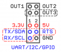
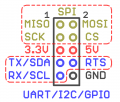
Connector Mod1, Mod2 and Mod3 WB6.7 for expansion modules
Connector Mod4 WB6.7 for extension modules
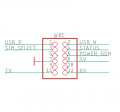
Slot WBC connector on the WB6.7 for 2g/3g/4g modems


Signals on expansion modules
| Output sodim | GPIO | GPIO number | Pinmux pad name | Pin | Function |
| MOD1 | |||||
| - | - | - | - | 3.3V | 3.3V |
| 30 | GPIO1_IO24 | 24 | UART3_TX_DATA | TX | gpio/uart_tx/i2c_sda |
| 32 | GPIO1_IO25 | 25 | UART3_RX_DATA | RX | gpio/uart_rx/i2c_scl |
| - | - | - | - | 5V | 5V |
| 34 | GPIO1_IO26 | 26 | UART3_CTS_B | RTS | gpio/uart_de |
| - | - | - | - | GND | GND |
| MOD2 | |||||
| - | - | - | - | 3.3V | 3.3V |
| 98 | GPIO4_IO21 | 117 | CSI_DATA00 | TX | gpio/uart_tx/i2c_sda |
| 49 | GPIO1_IO10 | 10 | JTAG_MOD | TX (muxed through 3k, 12k PD) | spdif out |
| 100 | GPIO4_IO22 | 118 | CSI_DATA01 | RX | gpio/uart_rx/i2c_scl |
| - | - | - | - | 5V | 5V |
| 52 | GPIO1_IO09 | 9 | GPIO1_IO09 | RTS | gpio/uart_de |
| - | - | - | - | GND | GND |
| MOD3 | |||||
| - | - | - | - | 3.3V | 3.3V |
| 90 | GPIO4_IO17 | 113 | CSI_MCLK | TX | gpio/uart_tx/i2c_sda |
| 92 | GPIO4_IO18 | 114 | CSI_PIXCLK | RX | gpio/uart_rx/i2c_scl |
| - | - | - | - | 5V | 5V |
| 94 | GPIO4_IO19 | 115 | CSI_VSYNC | RTS | gpio/uart_de |
| - | - | - | - | GND | GND |
| MOD4 | |||||
| - | - | - | - | 3.3V | 3.3V |
| 194 | GPIO3_IO21 | 85 | LCD_DATA16 | TX | gpio/uart_tx/i2c_sda |
| 192 | GPIO3_IO22 | 86 | LCD_DATA17 | RX | gpio/uart_rx/i2c_scl |
| 112 | GPIO4_IO28 | 124 | CSI_DATA07 | MISO | spi miso |
| 106 | GPIO4_IO25 | 121 | CSI_DATA04 | SCK | spi sck |
| - | - | - | - | 5V | 5V |
| 150 | GPIO3_IO0 | 64 | LCD_CLK | RTS | gpio/uart_de |
| - | - | - | - | GND | GND |
| 110 | GPIO4_IO27 | 123 | CSI_DATA06 | MOSI | spi mosi |
| 108 | GPIO4_IO26 | 122 | CSI_DATA05 | SS | spi ss |
| WBC (modem) | |||||
| 188 | GPIO3_IO24 | 88 | LCD_DATA19 | SIM_SELECT | SIM slot select (low: 1, high: 2) |
| 166 | GPIO3_IO19 | 83 | LCD_DATA14 | STATUS | Modem power status (input) |
| 164 | GPIO3_IO20 | 84 | LCD_DATA15 | POWER_GSM | Modem PWRKEY (output) |
| 125 | GPIO5_IO04 | 132 | SNVS_TAMPER4 | 5V | gpio (on/off 5V to modem) |
| 186 | - | - | LCD_DATA20 | TX | uart_tx |
| 184 | - | - | LCD_DATA21 | RX | uart_rx |
| - | - | - | - | GND | GND |
ADC channels
| termonal | ADC chanel | Divisor |
|---|---|---|
| A1 | 4 | 88k7, 10k |
| A2 | 2 | |
| A3 | 1 | |
| A4 | 3 | |
| Vin | 8 | 200k, 12k |
| 5Vout | 5 | 33k, 12k |
Legs for internal use
| sodim output | GPIO | GPIO number | output i.mx6UL | function |
|---|---|---|---|---|
| 84 | GPIO1_IO13 | 13 | JTAG_TDI | transistor lift 1-wire to the top (W2) |
| 77 | GPIO4_IO16 | 112 | NAND_DQS | transistor lift 1-wire to the top (W1) |
| 36 | GPIO1_IO27 | 27 | 5V out | |
| 23 | GPIO2_IO19 | 51 | SD1_DATA1 | watchdog input (6.7-6.8) |
| ? | GPIO3_IO08 | - | LCD_DATA03 | watchdog input (6.9-) |
| 162 | PWM1_OUT | LCD_DATA00 | Buzzer | |
| 80 | Red LED, indicator controlling | |||
| 82 | Green LED, indicator controlling | |||
| 65 | GPIO1_IO18 | 18 | STAT1 (BATTERY_CHARGING) | |
| 67 | GPIO1_IO19 | 19 | STAT2 (BATTERY_PRESENT) | |
| 152 | GPIO3_IO10 | 74 | supply Wi-Fi (active low) | |
| 29 | GPIO2_IO16 | 48 | i2c for RTC, SDA | |
| 31 | GPIO2_IO17 | 49 | i2c for RTC, SCL | |
| 144 | GPIO3_IO12 | 76 | PAD_LCD_DATA07 | i2c for EEPROM1, SDA |
| 142 | GPIO3_IO03 | 67 | PAD_LCD_VSYNC | i2c for EEPROM1, SCL |
| 160 | GPIO3_IO06 | 70 | PAD_LCD_DATA01 | i2c for EEPROM2, SDA |
| 158 | GPIO3_IO07 | 71 | PAD_LCD_DATA02 | i2c for EEPROM2, SCL |
| 75 | GPIO4_IO11 | 107 | supply USB | |
| 154 | GPIO3_IO09 | 73 | V_OUT_ON | |
| 156 | GPIO3_IO08 | 72 | V_OUT_ST (6.7-6.8) | |
| 102 | GPIO4_IO23 | 119 | PAD_CSI_DATA02 | RS-485-1 failsafe bias |
| 96 | GPIO4_IO20 | 116 | CSI_HSYNC | RS-485-2 failsafe bias |
| 40 | GPIO1_IO23 | 23 | PAD_UART2_RTS_B | CAN transciever power |
| 117 | GPIO5_IO00 | 128 | SNVS_TAMPER0 | Termination resistor on RS-485-1 |
| 121 | GPIO5_IO02 | 130 | SNVS_TAMPER2 | Termination resistor on RS-485-2 |
| GPIO5_IO10 | 138 | FW button |