Wiren Board 6: Hardware
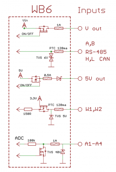
ADC Input protection
- Protection of all inputs against supply voltage (up to 40 V) and impulse noise.
- Supply polarity reverse protection.
- The protection of keys at the inputs Ax from the inductive load and from short-circuit currents.
Multifunctional inputs/outputs A1-A4
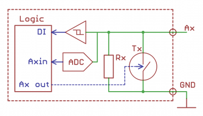
Multifunctional channels consist of parallel operating input and output stages.
The output stage consists of a switching Tx element . The Tx key closes the outputs to the ground. Under control of the controller logic schemes , the Tx switch can be in 2 states:
- Active: is closed; the channel output is 0.
- Inactive: open circuit; high impedance.
This type of output is called open collector.
The open collector outputs on the Ax channel are displayed in software as Ax_OUT. The path of the channel is: "wb-gpio/Ax_OUT".
For Ax channels, the input stage consists of an ADCx analog-to-digital converter and Rx input impedance (100 kΩ). The ADCx converter has a high input impedance, it is connected continuously and does not affect the channel operation in output mode. In the input mode, the Tx key is deactivated (open) and therefore does not affect the voltage measurement at the channel terminal. The input impedance of the channel is determined by the Rx resistor in input mode: if no other circuits are connected to the channel terminal, the resistor will "pull" the input voltage to "0 power", and the ADCx converter will assume the voltage to be 0. The analog inputs on the channels are displayed in Ax as an Ax section of the ADC. The channel path is: "wb-adc/Ax".
There is a function of binary input DI for Ax channels - the controller perceives the terminal voltage more than 3 V as a logical unit (input operation), and less than 1.5 V — as a logical zero. The binary inputs on the Ax channel are displayed as Ax_IN in software. The address of the binary input channel is "wb-gpio/Ax_IN".
Wx Inputs
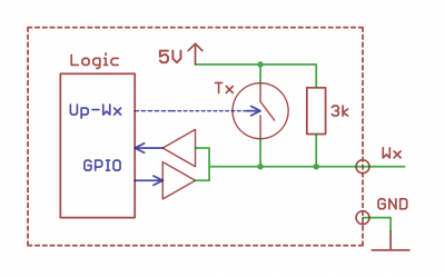
The main purpose of the WX inputs is to connect external temperature sensors via the 1-Wire bus. Since this is a bus, you can connect several devices to the same 1-Wire port.
See 1-Wire/en.
Wx can be used to connect discrete sensors. Wx channels are equipped with tightening to +5 V. Dry contact type inputs are connected between ground and Wx. The Wx output mode is set by the W1 terminal mode (W2 terminal mode) parameter: 1-Wire master or Discrete input in the Hardware Modules Configuration of the web interface.
+5 Vout power output
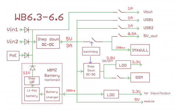
It is convenient to use +5V output to power the sensors. It is protected from short circuit and high voltage. When the controller is powered by a battery, the +5V output remains active. There is also a function of software control of this output — it can be disabled. In the Web interface the output control is realised through the 5V_OUT of the Discrete I/O device. The voltage of the channel is measured by the ADC.
Power supply output Vout
Для питания периферийных устройств можно использовать выход Vout. Он защищен от КЗ и подачи повышенного напряжения. При питании контроллера от аккумулятора на выход подается напряжение +11 В. Так же есть программное управление этим выходом — его можно отключать. В Web-интерфейсе выход представлен контролом V_OUT устройства Discrete I/O. Наличие напряжение показывает контрол V_OUT_OK. Напряжение на канале измеряется АЦП.
You can use the Vout output to power the peripherals. It is protected from short circuit and high voltage. When the controller is powered from the battery, the output voltage is +11 V. There is also a software control of this output — it can be disabled. In the Web interface the output control is realised through V_OUT of the Discrete I/O device. The control V_OUT_OK indicates the voltage presence. The voltage on the channel is measured by the ADC.
Attention! The input voltage is connected directly to the Vout terminal: make sure that the devices connected to it are rated for the appropriate voltage!
RS-485 line terminators
According to the RS-485 standard, the line must be terminated with 100 — 120 Ohm resistors at both ends. To simplify installation, the controller has built-in terminators, which can be activated by jumpers of RS-485 (1 or 2) TERM on the front terminal panel of the controller.
Also there are the protective resistors of the offset on the lines, fail safe bias,(stretching of lines A and B) are enabled by default. If the controller is used in the "slave" mode, then these resistors must be disabled (done by software control of the corresponding GPIOs: RS-485-1 failsafe bias and RS-485-2 failsafe bias).
Power Supply
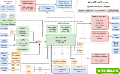
The Wiren Board 6 has four external inputs for connecting of power supplies: DC jack, 2 terminals and Passive PoE. It is possible to simultaneously connect sources to different inputs, including different voltages.
External power supply
The permissible power range is 9-36 V (when using the battery module 12 — 36 V), 9 — 48 V in the new revisions; the voltage range is indicated on the controller label. The average consumption is 1.5-2W, but since the GSM module consumes up to 8W impulsively, it is recommended to use power supplies with a power of at least 10W.
Разъем питания под стандартный Jack 5,5 x 2,1 мм, также входное напряжение можно подключать к клеммам Vin и GND. Блок клемм питания содержит две клеммы Vin, к которым можно подключить два независимых блока питания для резервирования. Земли блоков питания должны быть объединены и подключены к клемме GND.
Power over Ethernet
Поддерживается питание по кабелю Ethernet. Подробнее смотрите Power over Ethernet. Оба разъема поддерживают Passive PoE, соответствующие контакты разъемов соединены напрямую — при подаче питания на один разъем, напряжение появляется и на другом: это обеспечивает передачу питания Passive PoE на устройства, подключенные к другому порту Ethernet.
Аккумулятор
Wiren Board позволяет подключить внутренний модуль резервного питания WBMZ2-BATTERY с Li-Ion (Li-Pol) аккумулятором. При снижении напряжения Vin ниже 11 В питание осуществляется от модуля резервного питания. На выход Vout подается 11 В. Его можно использовать для питания внешних модулей.
