Начальное конфигурирование устройств через web-интерфейс
Внимание: Отображаемое название «Начальное конфигурирование устройств через web-интерфейс» переопределяет ранее заданное отображаемое название «RS-485:Configuration via Web Interface». For general information on connecting RS-485 devices to the controller, see page RS-485.
Serial device configuration
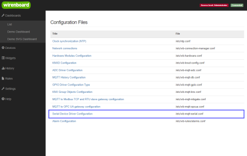
Go to the Configs page of the web interface, and click /etc/wb-mqtt-serial.conf (serial is the label of serial ports, RS-485 refers to them), or select Serial Device Driver Configuration on the left panel of the interface.
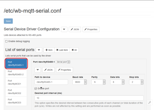
The serial ports configuration page will open. On the left, select the port to which you have connected the device. Ports are named in Linux terminology,- /dev/ttyXXXN; to understand which one is used, see Wiren_Board_5: Apparatures.
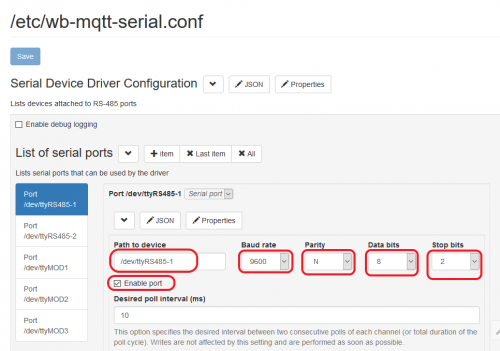
Port setting
Set the port settings: speed (bit/s), number of bits in the packet, whether there is a parity bit, the number of stop bits - this information is specified in the documentation for the peripheral equipment. Then be sure to tip Enable port (with this setting, the port can be disabled if any hardware on it starts to fail).
NB. If you connect multiple devices to the same controller port, these settings must match.
Adding devices
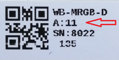
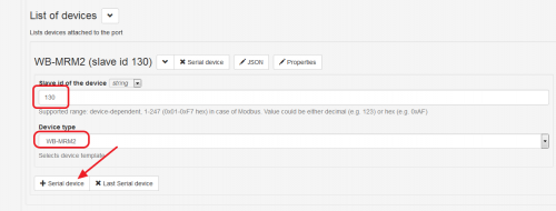
Go to List of devices below. Press the + Serial Device button to add a device. Select the type of device (usually corresponds to the model of the device) and specify its address (usually indicated by the documentation for the device, for devices of our production is indicated on the body label in decimal format):
The device address is specified either in hexadecimal (starts with 0x..), or in decimal (as a normal number). Then be sure to click the blue Save button at the top of the page.
Checking the operation
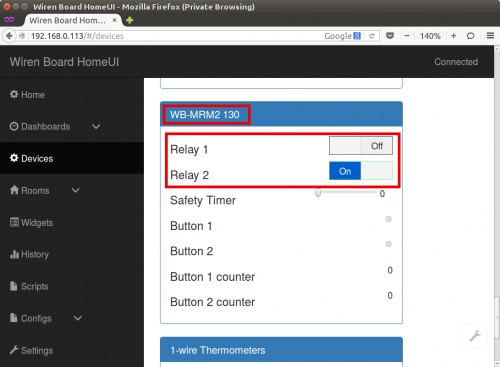
To check the operation of the device, go to the Devices page. It should display the unit corresponding to the connected device. In our example,a block WB-MRM2 130 appeared (template name - DEVICE_TYPE_ADDRESS) with two buttons to control the relay, two input indicators for buttons and push counters. You can press the button - the relay on the connected device will switch.
Adding a widget
For web interface version 1.x
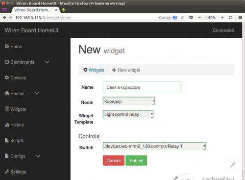
To add a control button to the Home page and name it according to its purpose (for example, The light in the corridor), you need to create a widget. To do this, go to the Widgets page and click the green add widget button. Then you need to enter the widget parameters: the name (as it is called in the interface), the room (the group to which the widget is attached; used to organize when there are many widgets - if not enough, you can choose any), and the type of widget - in our case, the relay controls the lighting, so choose Light Control Relay. After that, there is another option - you need to choose which device corresponds to the widget. All available devices of the selected type are shown in the list, their names are given in accordance with the terminology of MQTT. At the end, click Submit - the new widget will appear on the Widgets page.
Additional device settings
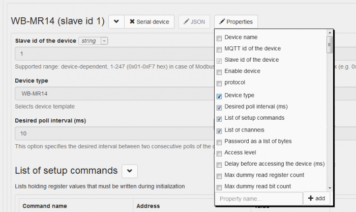
Additional device parameters can be set via the Properties button. Additional device configuration fields can be displayed in the drop-down menu.
The setup section (List of setup commands) is used to initialize certain device registers before operation. As an example, write the value 0 in the holding register of the WB-MR14 relay module to set the button control mode without locking for all inputs of the module. Click on the Properties button and select The list of setup commands checkbox. Click the Properties button again to hide the drop-down list.
Press the Save button and make sure that the module operates in the control mode of push-button switches. The device will have A list of setup commands section. Press the +Setup command button and proceed to creating the setup command. We need to specify the command name, the number of the Modbus register and the triggering value. Setup-initialization is performed once after the driver is loaded.
Setting the polling period
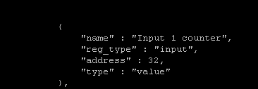
The driver ([wb-mqtt-serial|https://github.com/contactless/wb-homa-drivers/tree/master/wb-mqtt-serial wb-mqtt-serial]) allows you to determine what speed certain channels of the device will be polled at. This parameter is called Desired poll interval and is specified in milliseconds. Common to all the polling interval is specified by the Desired poll interval in the configuration of the port. If you do not override this setting in other devices or other channels, this value will be used for each channel. If the polling rate is set for a particular device, then it will be used for all channels of this device, again, if a channel does not have its own polling interval. The priority of intervals looks like this: channel-> device -> port. For example, if we have multiple relay module inputs that are time-critical, we can set a minimum interval of 1 MS for them. By default, there is no field in the web interface to change this property -- it must be added. First, we specify the channel whose property we want to override by clicking the +Item button. The control name and address can be found in the device template file
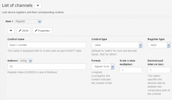
In the 'Control name' field we substitute the value of the variable "name", Address -- "address". This way we fill in fields Control type and Register type.
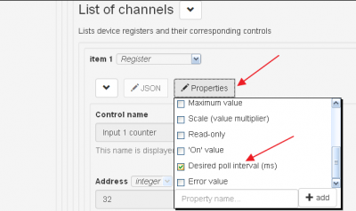
Click on the Properties button of the corresponding channel and put a check mark in the Desired poll interval (ms), as shown in the figure. The result is the following set of fields:
To save, click the Save button at the top of the page.
