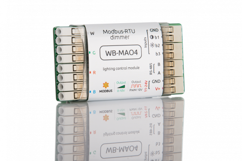
WB-MAO4 Modbus Dimmer
The page is in development!
Purpose
4-channel lighting control module is designed to control lamps with interfaces 0-10V, PWM, as well as to control arbitrary load with the corresponding inputs.
The type of output signal: 0-10V or PWM c with an amplitude of 10V. Type of output signals is configured (for all channels at once).
The module is controlled from the controller or PC via the RS-485 bus by MODBUS commands, as well as by external buttons.
Technical specifications
- 4 channels 0-10V or 10V PWM
- PWM frequency up to 400 Hz.
- Supply voltage: 11 to 24 V.
- Power consumption: 0.3 W.
- Interface: RS485, Modus RTU
- RS-485 interface parameters are set programmatically (see register Card);
default: speed — 9600 bit/s; data — 8 bit; parity bit — no (N); stop bits — 2 - Save state when power is off
- Inputs for three buttons for channel control
- Size– 65*35*7 mm.
Operating conditions
- Air temperature from -40°C to +70°C;
- Relative humidity up to 95%, without moisture condensation.
Connection
The module is made in the unselfish version - the board is in a shrink tube.
RS-485 and control buttons are connected to the blue terminals:
- A and B - RS485 signal lines
- GND - ground RS-485 bus (if any)
- b1 and GND - color balance control button
- b2 and GND - brightness control button
Management
Bus parameters
Speed is 9600 bit/s, data - 8 bit, parity – no, stop bit - 2.
Commands supported by device
| Command | command (dec) |
|---|---|
| READ_COIL | 1 |
| WRITE_SINGLE_COIL | 5 |
| WRITE_MULTI_COILS | 15 |
| READ_HOLDING_REGISTERS | 3 |
| WRITE_SINGLE_REGISTER | 6 |
| WRITE_MULTI_REGISTERS | 16 |
Functions
Address change is broadcast (slave_id 0) team record (WRITE_SINGLE_REGISTER) to holding register with address 128 (0x80).
6 bytes signature lies at the address 200. The signature is unique for each device model and allows you to identify the model. To obtain the signatures necessary to fulfill READ_HOLDING_REGISTERS address 200 length 6. Writing to this area of memory is not supported and error 3 is returned when attempting to write to an invalid location.
LED control
The brightness of the channel is set by an 8-bit number (0-255). The physical brightness of the LEDs is set according to the logarithmic dimming curve.
The module uses pulse width modulation (PWM), bit depth: 12 bit, PWM frequency: 24 kHz.
"The page is under development!"
The module has inputs for three hardware buttons.
Button 1. Short press – turns all channels on/off. Long press – smoothly change the brightness of all channels.
Button 2. Long press the button – smooth color change.
You can disable channel management using the buttons by writing 255(0xFF) to HOLDING_REGISTER at address 5.
In any operating mode, the current status of the buttons can be read from HOLDING_REGISTER at 6 and 7. 0 - button unpressed, 1 - pressed.
Register map
| Register / address | type | read-write | default | format | Purpose | Note |
|---|---|---|---|---|---|---|
| 0 | holding | RW | - | 0-255 | Channel level G, logarithmic curve | |
| 1 | holding | RW | - | 0-255 | the Level of the R channel, the logarithmic curve | |
| 2 | holding | RW | - | 0-255 | Channel B Level, logarithmic curve | |
| 5 | holding | RW | 0 | 0: standard mode, 0xFF: disable control | button operation mode | |
| 6 | input | R | 1 - pressed, 0 - unpressed | the state of the button 1 | ||
| 7 | input | R | 1 - pressed, 0 - unpressed | button status 2 | ||
| 9 | holding | RW | 74 (312.5 Hz) | freq = 24 kHz / (value + 1) | PWM frequency | |
| 13 | holding | RW | 100 | x 10ms | Smooth color change time | |
| 0 | coil | RW | 0 | 0: 0-10V
1: PWM 10V |
Output mode | |
| 120 (0x78) | holding | RW | 0 | 0 | write to the register causes a stateless reboot of the module | not supported |
| 121 (0x79) | input | R | - | mV | current supply voltage of the module | not supported |
| 128 (0x80) | holding | RW | 1 | Modbus device address | everything | |
| 200-206 | input | R | {'W','B','M','A,'O', 0} | | / | signature | everything | |
| 220-241 | input | | | | _date__ _time__ | firmware build date | everything |
