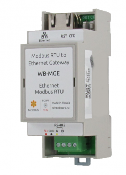
WB-MGE
Purpose
WB-MGE interface converters are designed for remote connection of Modbus RTU devices with RS-485 interface via Ethernet (Modbus RTU over TCP Protocol). It is possible to connect the controller directly to the module, as well as through the local network or the Internet.
Interface conversion
There are three modifications of WB interface converters: WB-MIO, WB-MIO-E and WB-MGE. The table below shows which interface each module converts to.
| Model | From | To | |||
|---|---|---|---|---|---|
| RS-485
(Modbus) |
Ethernet
(IP) |
WBIO | RS-485
(Modbus) |
Ethernet
(IP) | |
| WB-MIO | + | + | |||
| WB-MIO-E | + | + | + | ||
| WB-MGE | + | + | + | + | |
Technical specifications
| Option | Value |
|---|---|
| Power | |
| Supply voltage front-end | 9 V — 24 V DC |
| Power consumption |
0.85 W |
| Terminals and wire section | |
| Recommended wire cross-section, mm2 | 0,75 — 1 |
| Length of the standard sleeve , mm | 8 |
| Torque of screws, N∙m | 0,2 |
| Communication | |
| Communication protocol | Modbus RTU |
| Interfaces |
|
| RS-485 interface parameters | set programmatically, by default:
speed 9600 bps; data bits 8; parity N; stop bits 2;
|
| dimensions | |
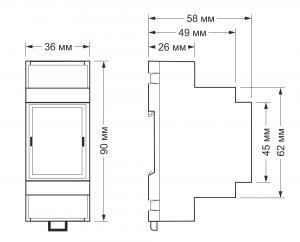
| Size | 2 DIN; 36,3x90,2x57,5 mm |
| Operating conditions | |
| Air temperature | -40°C to +80°C |
| Relative humidity | up to 92%, no condensation |
The Ethernet connection and the module network settings
The WB-MGE module connects to the local Ethernet network to the router port or directly to one of the Ethernet ports of the Wireless Board programmable controller. Power is supplied to the V+ and GND terminals of the WB-MGE module. The module does NOT support PoE power.
On the default Ethernet network, WB-MGE has a static IP address of 192.168.0.7. Attention: if the local network uses a range of addresses other than 192.168.0.0/24, then when connecting through the router communication with the device will disappear and additional configuration will be required. Detailed instructions on configuring the Ethernet part of WB-MGE can be found on configuring Ethenet interfaces and connecting WB-MIO-E and WB-MGE modules.
The Modbus-registers
A description of the registers can be found on WB-MIO and WB-MIO-E interface Converters in the "Modbus Control" section.
Images and drawings of the device
По ссылкам ниже вы можете скачать изображения и чертежи устройства WB-MGE.
Corel Draw 2018: WB-MGE.cdr.zip
Corel Draw PDF: WB-MGE.cdr.pdf
Autocad 2013 DXF: WB-MGE.dxf.zip
Autocad PDF: WB-MGE.pdf

