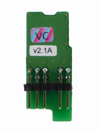
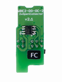
Wiren Board 6: Open colletor outputs module (WBE2-DO-OC-2)
The module is designed to control the inputs of the "dry contact" type, as well as for switching low-voltage load in tasks where galvanic isolation is required.
Technical specifications
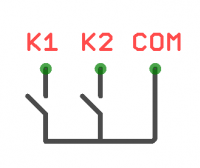
The module contains two N-channel transistors with common ground.
Each channel has built-in protection against voltage surges when switching inductive load (TVS at 30V).
The ground (GND) of the load must be connected to the GND terminal of the module (O3 terminal of the extension module).
| Parameter | Value |
|---|---|
| Number of outputs | 2 |
| Outputs type | N-channel field effect transistor
(open collector) |
| Contact configuration | SPST (normally open) |
| Maximum switching voltage | 40V DC |
| Maximum switching current, per channel | 1A |
| The channel resistance in the open state | 200 mOhm |
| Voltage isolation between the controller and the output | no |
| Maximum power consumption | 0.01 W |
| Compatibility | Compatiblу with Wiren Board 6 of all revisions. |
Pinout
| Terminal | Function |
|---|---|
| O1 | K1 |
| O2 | K2 |
| O3 | GND |
Configuration
Configuration is carried out in the web interface, section Configs => Hardware Modules Configuration.
Select "WBE2-DO-OC-2: Dual Open-Collector Output Module" in the Internal slot 1 or 2 section (depending on the slot number) and click Save.
Once added, two additional outputs appear in the Devices next to the controller outputs (the Discrete I/O section).
Device is detected immediately, reboot is not required.
MQTT
| Slot | Terminal | Output | Channel (MQTT) | Topic (MQTT) |
|---|---|---|---|---|
| MOD1 | O1 | K1 | wb-gpio/MOD1_K1 | /devices/wb-gpio/controls/MOD1_K1 |
| O2 | K2 | wb-gpio/MOD1_K2 | /devices/wb-gpio/controls/MOD1_K2 | |
| MOD2 | O1 | K1 | wb-gpio/MOD2_K1 | /devices/wb-gpio/controls/MOD2_K1 |
| O2 | K2 | wb-gpio/MOD2_K2 | /devices/wb-gpio/controls/MOD2_K2 |
Connection order
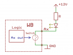
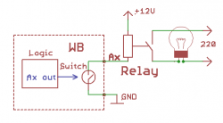
The load is connected as follows: "+" of the load is connected to the power supply, "-" is connected to the transistor output. For the load to start working, you need to apply a high level to the gate of the transistor.
The illustrations show the wiring diagrams of the led and relay.
