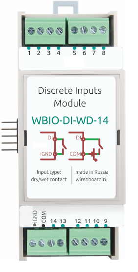
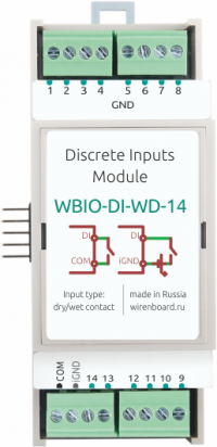
Universal module of disctere inputs (WBIO-DI-WD-14)
Внимание: Отображаемое название «Universal module of disctere inputs (WBIO-DI-WD-14)» переопределяет ранее заданное отображаемое название «WBIO-DI-WD-14 I/O Module».
WARNING: In the first versions of the module, the COM and iGND terminals are swapped on the device. So does their purpose. Pay attention to the label with signatures and wiring diagram.
Purpose
Designed for connection of pulse counters, buttons, switches, sensors with dry contact output. Discrete signals input, circuit integrity control etc. Module combines the functions of the WBIO-DI-LVD-x and WBIO-DI-DR-x product line devices.
Specifications
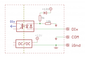
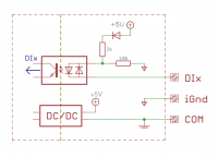
Contains 14 universal inputs for connecting dry contacts and determining the presence of low voltage with group galvanic isolation. The mode of operation depends on the selected scheme of connection.
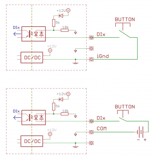
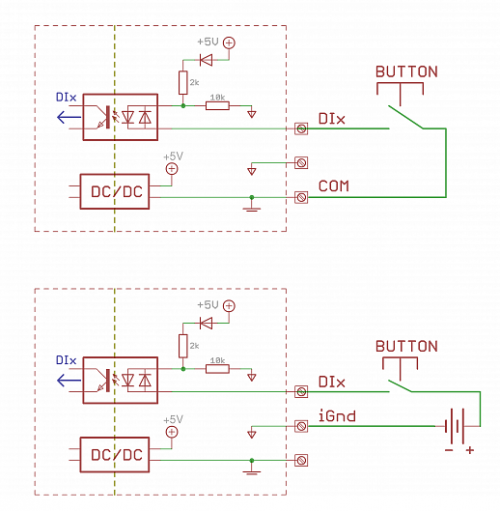
The terminals are supplied with a voltage of about 5 V relative to the output iGND (COM in the old version of the module), when the inputs are closed, a small current (2 mA) is supplied to this output, causing the input to be triggered.
Also, the input is triggered when an external voltage (both polarities, as well as AC 50Hz) between the input and COM (iGnd in the old version of the module).
It is possible for module to work simultaneously in two modes.
| Parameter | Value |
|---|---|
| Number of inputs | 14 |
| Isolated input groups | 1 |
| Input type | dry contact/voltage availability |
| dry contact Mode" | |
| Operation condition | circuit input to iGND (COM in older versions of the module) or the presence of voltage between the input and the "'COM"' (iGND in the old version of module) |
| Tripping current | 1 mA |
| Voltage of "wetting" | 5V |
| voltage availability mode | |
| Operating voltage
(both polarities) |
|
| Rated voltage | 12 — 24 V AC/DC |
| Maximum permissible voltage | 50 V AC/DC |
| General | |
| Minimum pulse width to trigger | 10 MS |
| Minimum time between consecutive signals | 20 MS |
| Module type | "I" (inverted address scheme) |
| Power consumption | 0.1 W |
| Width, DIN units | 2 |
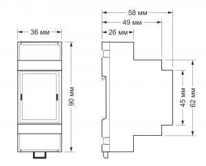
| Size | 36,3x90,2x57,5 mm |
| Terminals and wire section | |
|---|---|
| The recommended wire cross section with pin bushing insulated tip, mm2 | 0,75 — 1 |
| Standard sleeve length of pin bushing insulated tip, mm | 8 |
| Tightening torque of screws, Н∙м | 0,2 |
Connection to controller
See section activating the module in the web interface of the controller.
External device connection
Sensors/counters with pulse outputs/buttons.
Such devices form a signal by closing two wires connected to them. Connect one wire to the iGND terminal (COM in the old version) of the module. Connect the second wire to the Dx terminal. Some counters have a pulse output on the optocoupler, then the two wires have polarity - "plus" and "minus". The "minus" connects to iGND(COM in the old version), "plus" -to Dx.
Devices with open collector output.
Connect the ground of the device to the iGND terminal (COM in the old version) of the module. Connect the open collector output to the Dx terminal.
The module inputs are galvanically isolated from the controller. Therefore, the ground of the connected device and the controller may be different.
Device pictures and drawings
Corel Draw 2018: Мы еще не подготовили рисунок этого устройства. Вы можете запросить рисунок устройства "Модуль дискретных входов для сигналов "сухой контакт" WBIO-DI-WD-14" на портале техподдержки Wiren Board (необходима регистрация).
Autocad 2013 DXF: WBIO-DI-WD-14.dxf.zip
Autocad PDF: WBIO-DI-WD-14.pdf
