WB-mqtt-serial driver: examples of writing templates

Материал из Wiren Board
Это утверждённая версия страницы. Она же — наиболее свежая версия.
Другие языки:

The general structure of the device template

A device template file is a JSON structure that describes device parameters. The template allows comments. The JSON structure is written inside the space between the opening and closing braces: { ... }


The general structure of the device template is as follows:

//Device template
{ 
"device": {
    "Device1 parameter":"value", 
    "Device2 parameter":"value", 
    ...
    "channels": [ {channel parameters 1}, {channel parameters 2}, ...]
    }
}

Device is a device connected to the controller, channel is a data source: usually it is a Modbus register with a description of the data type, polling frequency, value conversion, etc. See the following sections for a detailed description: template files are stored on the controller in a folder

/usr/share/wb-mqtt-serial/templates

You should copy the new templates you created for the new device to this directory. In our templates, we use indents of 4 spaces per level, which ensures the readability of the template code, and we recommend writing new templates with the same indentation.

Device settings
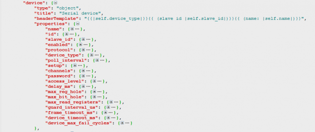
Device parameters are described in wb-mqtt-serial.schema.json (made via Collapsible JSON Formatter)

The parameters of the device are set in the form of a set of pairs key:value at the beginning of the pattern. Required parameters are "device_type" and "device" keys.

The device_type key specifies a unique name for the device type as a string, for example:

"device_type":"WB-MAP12H",

.

The device key value is a composite structure that describes specific device parameters:

"device": {
        "name": "WB-MAP12H",
        "id": "wb-map12h",
        "channels": [...]
        }


  • name — is the displayed name of the device. Published as .../meta/name in mqtt. The device name is used when displaying the web-interface, stored in the topic "id" + " " + "slave_id". Example for a device with modbus address 5 (slave_id) and value "name":"WB-MAP12H (basic)" /devices/wb-map12h_5/meta/name WB-MAP12H (basic).
  • id — is the unique identifier of the device to MQTT. Each item in devices must have a unique id. mqtt-topic related to this device in MQTT have a common prefix /devices/<topic ID>/... Also by default it is taken from the template with the addition of slave_id: "id" + "_" + slave_id


  • channels — is the list of device channels, is set as [...], each element represents a description of a particular channel.

Other device parameters are either added to the section when the template is included in the wb-mqtt-serial general configuration, or default values are used. The full list can be found in the wb-mqtt-serial.schema.json file (a copy is also stored on the controller: /usr/share/wb-mqtt-confed/schemas/wb-mqtt-serial.schema.json). See "device" object properties: "device" -> "properties".

Device channels
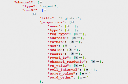
Channel parameters are described in wb-mqtt-serial.schema.json (made in app Collapsible JSON Formatter)

Channel description is a structure

"channels": [
        {
            "name": "Channel name1",
            ...
        },
        {
            "name": "Channel name2",
            ...
        },
        ...
    ]

The structure contains the following set of fields.
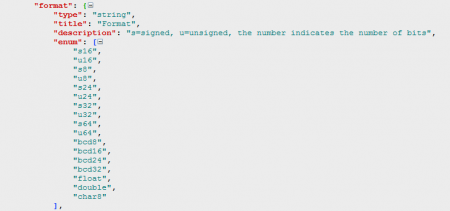
the format of data representation in Modbus-registers is described in wb-mqtt-serial.schema.json (made in app Collapsible JSON Formatter)
  • name — имя канала, уникальное для устройство имя канала
  • reg_type — тип Modbus-регистра, одно из "coil", "discrete", "holding", "holding_single", "holding_multi", "input", "direct"
  • address — адрес Modbus-регистра, связанного с каналом.
  • type — тип контрола -- виртуального элемента для представления данных в Web-интерфейсе контроллера: "switch", "pushbutton", "range", "rgb" и другие; полностью перечислены в схеме wb-mqtt-serial.schema.json.
  • readonly — "true", если значения можно только считывать.
  • format — тип переменной, описывающей значение, см. рис.
  • name — the channel name that is unique to the device
  • reg_type — type of Modbus register, one of "coil", "discrete", "holding", "holding_single", "holding_multi", "input", "direct" types
  • address — the address of the Modbus register associated with the channel.
  • type — type of control, a virtual element for data representation in the Web-interface of the controller: "switch", "pushbutton", "range", "rgb" and others; fully listed in the scheme wb-mqtt-serial.schema.json.
  • readonly — "true" if the values can only be read.
  • formattype of the variable describing the value, see figure.

In the simplest case, the fields "name", "reg_type", "address" and "type"are sufficient. Descriptions of other parameter types are fully listed in the wb-mqtt-serial.schema.json scheme.

Examples of device templates

The following are sample template files for some Wiren Board devices, covering a basic list of options used when creating templates.


WB-MS-THLS v.2

The WB-MS device is a universal combined Modbus sensor for temperature, humidity, lighting and sound pressure. The device provides access to data via Modbus input registers. The initial settings of the device are recorded in the holding registers, but are not used to obtain data and control the device, so the template is not included.You can see the full template code via the following link.

{
    "device_type": "WB-MS-THLS v.2",
    "device": {
        "name": "WB-MS / WB-MSW",
        "id": "wb-ms-thls-v2",
        "max_read_registers": 0,
        "channels": [
            {
                "name": "Temperature",
                "reg_type": "input",
                "address": 0,
                "type": "temperature",
                "format": "s16",
                "scale": 0.1,
                "error_value": "0x7FFF"
            },
            {
                "name": "Humidity",
                "reg_type": "input",
                "address": 1,
                "type": "rel_humidity",
                "scale": 0.1,
                "error_value": "0xFFFF"
            },
            {
                "name": "Illuminance",
                "reg_type": "input",
                "address": 2,
                "type": "lux"
            },
            {
                "name": "Sound Level",
                "reg_type": "input",
                "address": 3,
                "scale": 0.01,
                "type": "sound_level"
            },
            {
                "name": "Input Voltage",
                "reg_type": "input",
                "address": 121,
                "scale": 0.001,
                "type": "voltage"
            },
            {
                "name": "External Sensor 1",
                "type": "temperature",
                "reg_type": "input",
                "address": "6",
                "format": "s16",
                "scale": 0.0625,
                "error_value": "0x7FFF"
            },
            {
                "name": "External Sensor 2",
                "type": "temperature",
                "reg_type": "input",
                "address": "7",
                "format": "s16",
                "scale": 0.0625,
                "error_value": "0x7FFF"
            }
        ]
    }
}

There is an interesting parameter in the settings of the device:

    "max_read_registers": 0,

This parameter describes the maximum number of registers that can be read from the device when requested. The default value is 1, in our case we specify to read all registers in one pass (bulk read).

In the settings of the channel "Temperature" there are three parameters that are worth paying attention to:

    "format": "s16",
    "scale": 0.1,
    "error_value": "0x7FFF"

Parameter"format": "s16" indicates that the number in the registers is represented as a signed 16-bit integer, "scale": 0.1 — indicates that the value obtained from the registers should be multiplied by the scaling factor 0.1 to obtain the temperature value, and the parameter "error_value": "0x7FFF" sets the value sent from the register, indicating that an error occurred during the sensor poll. This parameter will be highlighted in red in the web interface of the controller. You should use this option if you know what value your device sends in case of an error.


==== WB-MRGBW-D ==== WB-MRGBW-D is a four channel dimmer to control the led strip. Can control RGB+W tape or four single color tapes independently. Brightness settings are stored in holding registers; the template describes which registers can be changed to get the desired brightness of the channels, track the dimmer button presses and get the value of the number of clicks.You can see the full template code via the following link.

{
    "device_type": "WB-MRGBW-D", 
    "device": {
        "name": "WB-MRGBW-D", 
        "id": "wb-mrgbw-d", 
        "max_read_registers": 0, 
        "channels": [
            {
                "name": "RGB", 
                "type": "rgb", 
                "consists_of": [
                    {
                        "reg_type": "holding", 
                        "address": 1
                    }, 
                    {
                        "reg_type": "holding", 
                        "address": 0
                    }, 
                    {
                        "reg_type": "holding", 
                        "address": 2
                    }
                ]
            }, 
            {
                "name": "White", 
                "reg_type": "holding", 
                "address": 3, 
                "type": "range", 
                "max": 255
            }, 
            {
                "name": "Button 1", 
                "reg_type": "holding", 
                "readonly": true, 
                "address": 6, 
                "type": "switch"
            }, 
            {
                "name": "Button 2", 
                "reg_type": "holding", 
                "readonly": true, 
                "address": 7, 
                "type": "switch"
            }, 
            {
                "name": "Button 3", 
                "reg_type": "holding", 
                "readonly": true, 
                "address": 8, 
                "type": "switch"
            }, 
            {
                "name": "Button 1 counter", 
                "reg_type": "holding", 
                "readonly": true, 
                "address": 32, 
                "type": "value"
            }, 
            {
                "name": "Button 2 counter", 
                "reg_type": "holding", 
                "readonly": true, 
                "address": 33, 
                "type": "value"
            }, 
            {
                "name": "Button 3 counter", 
                "reg_type": "holding", 
                "readonly": true, 
                "address": 34, 
                "type": "value"
            }, 
            {
                "name": "Serial NO", 
                "type": "text", 
                "reg_type": "holding", 
                "address": 270, 
                "format": "u32"
            }
        ]
    }
}

In this template, the RGB composite channel sets the brightness of three color ribbon components stored in three holding registers at the same time and is described as follows:

    {
        "name": "RGB", 
        "type": "rgb", 
        "consists_of": [
            {
                "reg_type": "holding", 
                "address": 1
            }, 
            {
                "reg_type": "holding", 
                "address": 0
            }, 
            {
                "reg_type": "holding", 
                "address": 2
            }
        ]
    },

The white channel is controlled separately,

    {
        "name": "White", 
        "reg_type": "holding", 
        "address": 3, 
        "type": "range", 
        "max": 255
    },

The maximum value that can be set for the white brightness slider is 255:

"max": 255

The serial number of the device (channel "Serial NO") is read as an unsigned 32-bit integer:

"format": "u32"

WBIO-DO-R10A-8

Устройство WBIO-DO-R10A-8 — is a relay side module that connects directly to the controller's WBIO connector and is not Modbus controlled. But when it is connected via a WB-MIO or WB-MIO-E expansion device, it becomes a full-fledged Modbus device for which there is a corresponding template.You can see the full template code via the following link.

{
    "device_type": "WBIO-DO-R10A-8",
    "device": {
        "name": "WBIO-DO-R10A-8",
        "id": "wb-mio-gpio",
        "protocol": "modbus_io",
        "stride": 1000,
        "shift": 500,
        "max_read_registers": 0,
        "setup": [
            {
                "title": "IODIR",
                "address": 10000,
                "value": "0x0000"
            },
            {
                "title": "IPOL",
                "address": 10001,
                "value": "0x0000"
            },
            {
                "title": "GPINTEN",
                "address": 10002,
                "value": "0xffff"
            },
            {
                "title": "DEFVAL",
                "address": 10003,
                "value": "0x0000"
            },
            {
                "title": "INTCON",
                "address": 10004,
                "value": "0x0000"
            },
            {
                "title": "IOCON",
                "address": 10005,
                "value": "0x4444"
            },
            {
                "title": "FLAG",
                "address": 9999,
                "value": 1
            }
        ],
        "channels": [
            {
                "name": "K1",
                "reg_type": "coil",
                "address": 0,
                "type": "switch"
            },
            {
                "name": "K2",
                "reg_type": "coil",
                "address": 1,
                "type": "switch"
            },
            {
                "name": "K3",
                "reg_type": "coil",
                "address": 2,
                "type": "switch"
            },
            {
                "name": "K4",
                "reg_type": "coil",
                "address": 3,
                "type": "switch"
            },
            {
                "name": "K5",
                "reg_type": "coil",
                "address": 4,
                "type": "switch"
            },
            {
                "name": "K6",
                "reg_type": "coil",
                "address": 5,
                "type": "switch"
            },
            {
                "name": "K7",
                "reg_type": "coil",
                "address": 6,
                "type": "switch"
            },
            {
                "name": "K8",
                "reg_type": "coil",
                "address": 7,
                "type": "switch"
            }
        ]
    }
}


In this template, you should pay attention to the following device settings.

    "protocol": "modbus_io",
    "stride": 1000,
    "shift": 500,
    "max_read_registers": 0,
    "setup": [

Option protocol: modbus_io indicates that the device connects to the extension module via special protocol. The parameters "stride": 1000 and "shift":500 set the shift of registers depending on the order in which the modules are connected to the extension module.


Shift = (((SlaveId.Secondary - 1) % 4) + 1) * DeviceConfig()->Stride + DeviceConfig()->Shift; Here stride — DeviceConfig()->Stride, a shift — DeviceConfig()->Shift.

Register shift (the number to be added to the base register number) is calculated by the formula:

Shift = (((SlaveId.Secondary - 1) % 4) + 1) * DeviceConfig()->Stride + DeviceConfig()->Shift;

Здесь stride — DeviceConfig()->Stride, a shift — DeviceConfig()->Shift. Each connected device has a serial number (SlaveId.Secondary) starting with 1 for the first device. (Here the sign "%" shows modulу division.)


For example, substituting the values of shift and stride in the formula:

Shift = ((( 1 - 1) % 4) + 1) * 500 + 1000 = (0 + 1) * 500 + 1000 = 1500

So, you need to add 1500 to all registers specified in the template.

Another important parameter — setup-section, array

     "setup": [    {
             "title": "IODIR",
             "address": 10000,
             "value": "0x0000"
         },
     {},
     ...]

It describes the registers and values that are entered once in these registers when the device is initialized (when WB-mqtt-serial is started or restarted). It can be used to configure devices to operate in a particular mode, set the initial values of brightness, servo position, relay status, mode of operation with the inputs of relay modules, etc.


WB-MAP3H

WB-MAP3H — three-channel electricity meter. It measures a large number of electrical network parameters. Since it can take quite a long time to poll all registers of such a device, there are several templates that contain the optimal set of parameters for the current task. We'll look at the basic pattern. You can see the full template code via the following link.

{
 "device_type": "WB-MAP3H (basic)", 
 "device": {
  "name": "WB-MAP3H (basic)", 
  "id": "wb-map3h", 
  "max_read_registers": 60, 
  "channels": [
   {
    "name": "Urms L1", 
    "reg_type": "input", 
    "address": "0x10d9", 
    "type": "voltage", 
    "format": "u16", 
    "scale": 0.01, 
    "round_to": 0.01
   }, 
   {
    "name": "THDN U L1", 
    "reg_type": "input", 
    "address": "0x10f1", 
    "type": "value", 
    "format": "u16", 
    "scale": 0.01, 
    "round_to": 0.01
   }, 
   {
    "name": "Urms L2", 
    "reg_type": "input", 
    "address": "0x10da", 
    "type": "voltage", 
    "format": "u16", 
    "scale": 0.01, 
    "round_to": 0.01
   }, 
   {
    "name": "THDN U L2", 
    "reg_type": "input", 
    "address": "0x10f2", 
    "type": "value", 
    "format": "u16", 
    "scale": 0.01, 
    "round_to": 0.01
   }, 
   {
    "name": "Urms L3", 
    "reg_type": "input", 
    "address": "0x10db", 
    "type": "voltage", 
    "format": "u16", 
    "scale": 0.01, 
    "round_to": 0.01
   }, 
   {
    "name": "THDN U L3", 
    "reg_type": "input", 
    "address": "0x10f3", 
    "type": "value", 
    "format": "u16", 
    "scale": 0.01, 
    "round_to": 0.01
   }, 
   {
    "name": "Frequency", 
    "reg_type": "input", 
    "address": "0x10f8", 
    "type": "value", 
    "format": "u16", 
    "scale": 0.01, 
    "round_to": 0.01
   }, 
   {
    "name": "Voltage angle L1", 
    "reg_type": "input", 
    "address": "0x10fd", 
    "type": "value", 
    "format": "s16", 
    "scale": 0.1, 
    "round_to": 0.01
   }, 
   {
    "name": "Voltage angle L2", 
    "reg_type": "input", 
    "address": "0x10fe", 
    "type": "value", 
    "format": "s16", 
    "scale": 0.1, 
    "round_to": 0.01
   }, 
   {
    "name": "Voltage angle L3", 
    "reg_type": "input", 
    "address": "0x10ff", 
    "type": "value", 
    "format": "s16", 
    "scale": 0.1, 
    "round_to": 0.01
   }, 
   {
    "name": "Irms L1", 
    "reg_type": "input", 
    "address": "0x10dd", 
    "type": "value", 
    "format": "u16", 
    "scale": 0.001, 
    "round_to": 0.01
   }, 
   {
    "name": "THDN I L1", 
    "reg_type": "input", 
    "address": "0x10f5", 
    "type": "value", 
    "format": "u16", 
    "scale": 0.01, 
    "round_to": 0.01
   }, 
   {
    "name": "P L1", 
    "reg_type": "input", 
    "address": "0x1302", 
    "type": "power", 
    "format": "s32", 
    "scale": 1.52588e-05, 
    "round_to": 0.01
   }, 
   {
    "name": "Q L1", 
    "reg_type": "input", 
    "address": "0x130a", 
    "type": "value", 
    "format": "s32", 
    "scale": 1.52588e-05, 
    "round_to": 0.01
   }, 
   {
    "name": "S L1", 
    "reg_type": "input", 
    "address": "0x1312", 
    "type": "value", 
    "format": "s32", 
    "scale": 1.52588e-05, 
    "round_to": 0.01
   }, 
   {
    "name": "PF L1", 
    "reg_type": "input", 
    "address": "0x10bd", 
    "type": "value", 
    "format": "s16", 
    "scale": 0.001, 
    "round_to": 0.01
   }, 
   {
    "name": "AP energy L1", 
    "reg_type": "input", 
    "address": "0x1204", 
    "type": "power_consumption", 
    "format": "u64", 
    "scale": 3.125e-05, 
    "round_to": 0.0001, 
    "word_order": "little_endian"
   }, 
   {
    "name": "RP energy L1", 
    "reg_type": "input", 
    "address": "0x1224", 
    "type": "value", 
    "format": "u64", 
    "scale": 3.125e-05, 
    "round_to": 0.0001, 
    "word_order": "little_endian"
   }, 
   {
    "name": "Irms L2", 
    "reg_type": "input", 
    "address": "0x10de", 
    "type": "value", 
    "format": "u16", 
    "scale": 0.001, 
    "round_to": 0.01
   }, 
   {
    "name": "THDN I L2", 
    "reg_type": "input", 
    "address": "0x10f6", 
    "type": "value", 
    "format": "u16", 
    "scale": 0.01, 
    "round_to": 0.01
   }, 
   {
    "name": "P L2", 
    "reg_type": "input", 
    "address": "0x1304", 
    "type": "power", 
    "format": "s32", 
    "scale": 1.52588e-05, 
    "round_to": 0.01
   }, 
   {
    "name": "Q L2", 
    "reg_type": "input", 
    "address": "0x130c", 
    "type": "value", 
    "format": "s32", 
    "scale": 1.52588e-05, 
    "round_to": 0.01
   }, 
   {
    "name": "S L2", 
    "reg_type": "input", 
    "address": "0x1314", 
    "type": "value", 
    "format": "s32", 
    "scale": 1.52588e-05, 
    "round_to": 0.01
   }, 
   {
    "name": "PF L2", 
    "reg_type": "input", 
    "address": "0x10be", 
    "type": "value", 
    "format": "s16", 
    "scale": 0.001, 
    "round_to": 0.01
   }, 
   {
    "name": "AP energy L2", 
    "reg_type": "input", 
    "address": "0x1208", 
    "type": "power_consumption", 
    "format": "u64", 
    "scale": 3.125e-05, 
    "round_to": 0.0001, 
    "word_order": "little_endian"
   }, 
   {
    "name": "RP energy L2", 
    "reg_type": "input", 
    "address": "0x1228", 
    "type": "value", 
    "format": "u64", 
    "scale": 3.125e-05, 
    "round_to": 0.0001, 
    "word_order": "little_endian"
   }, 
   {
    "name": "Irms L3", 
    "reg_type": "input", 
    "address": "0x10df", 
    "type": "value", 
    "format": "u16", 
    "scale": 0.001, 
    "round_to": 0.01
   }, 
   {
    "name": "THDN I L3", 
    "reg_type": "input", 
    "address": "0x10f7", 
    "type": "value", 
    "format": "u16", 
    "scale": 0.01, 
    "round_to": 0.01
   }, 
   {
    "name": "P L3", 
    "reg_type": "input", 
    "address": "0x1306", 
    "type": "power", 
    "format": "s32", 
    "scale": 1.52588e-05, 
    "round_to": 0.01
   }, 
   {
    "name": "Q L3", 
    "reg_type": "input", 
    "address": "0x130e", 
    "type": "value", 
    "format": "s32", 
    "scale": 1.52588e-05, 
    "round_to": 0.01
   }, 
   {
    "name": "S L3", 
    "reg_type": "input", 
    "address": "0x1316", 
    "type": "value", 
    "format": "s32", 
    "scale": 1.52588e-05, 
    "round_to": 0.01
   }, 
   {
    "name": "PF L3", 
    "reg_type": "input", 
    "address": "0x10bf", 
    "type": "value", 
    "format": "s16", 
    "scale": 0.001, 
    "round_to": 0.01
   }, 
   {
    "name": "AP energy L3", 
    "reg_type": "input", 
    "address": "0x120c", 
    "type": "power_consumption", 
    "format": "u64", 
    "scale": 3.125e-05, 
    "round_to": 0.0001, 
    "word_order": "little_endian"
   }, 
   {
    "name": "RP energy L3", 
    "reg_type": "input", 
    "address": "0x122c", 
    "type": "value", 
    "format": "u64", 
    "scale": 3.125e-05, 
    "round_to": 0.0001, 
    "word_order": "little_endian"
   }, 
   {
    "name": "Total P", 
    "reg_type": "input", 
    "address": "0x1300", 
    "type": "power", 
    "format": "s32", 
    "scale": 6.10352e-05, 
    "round_to": 0.01
   }, 
   {
    "name": "Total Q", 
    "reg_type": "input", 
    "address": "0x1308", 
    "type": "value", 
    "format": "s32", 
    "scale": 6.10352e-05, 
    "round_to": 0.01
   }, 
   {
    "name": "Total S", 
    "reg_type": "input", 
    "address": "0x1310", 
    "type": "value", 
    "format": "s32", 
    "scale": 6.10352e-05, 
    "round_to": 0.01
   }, 
   {
    "name": "Total PF", 
    "reg_type": "input", 
    "address": "0x10bc", 
    "type": "value", 
    "format": "s16", 
    "scale": 0.001, 
    "round_to": 0.01
   }, 
   {
    "name": "Total AP energy", 
    "reg_type": "input", 
    "address": "0x1200", 
    "type": "power_consumption", 
    "format": "u64", 
    "scale": 3.125e-05, 
    "round_to": 0.0001, 
    "word_order": "little_endian"
   }, 
   {
    "name": "Total RP energy", 
    "reg_type": "input", 
    "address": "0x1220", 
    "type": "value", 
    "format": "u64", 
    "scale": 3.125e-05, 
    "round_to": 0.0001, 
    "word_order": "little_endian"
   }, 
   {
    "name": "Phase angle L1", 
    "reg_type": "input", 
    "address": "0x10f9", 
    "type": "value", 
    "format": "s16", 
    "scale": 0.1, 
    "round_to": 0.01
   }, 
   {
    "name": "Phase angle L2", 
    "reg_type": "input", 
    "address": "0x10fa", 
    "type": "value", 
    "format": "s16", 
    "scale": 0.1, 
    "round_to": 0.01
   }, 
   {
    "name": "Phase angle L3", 
    "reg_type": "input", 
    "address": "0x10fb", 
    "type": "value", 
    "format": "s16", 
    "scale": 0.1, 
    "round_to": 0.01
   }
  ]
 }
}

What is so important in this template? First of all, we specify in the device parameters that no more than 60 registers should be read at the same time, so as not to stop for a long time the polling of other devices:

"max_read_registers" : 60. Also  the parameter describing the accumulated reactive energy in the phase L1  is indicative:
   {
    "name": "RP energy L1", 
    "reg_type": "input", 
    "address": "0x1224", 
    "type": "value", 
    "format": "u64", 
    "scale": 3.125e-05, 
    "round_to": 0.0001, 
    "word_order": "little_endian"
   },

Here you should pay attention to the fact that the address of the register can be set in hexadecimal form: "address": "0x1224" , the real scaling factor can be set in the exponential notation: "scale": 3.125 e-05', when reading the value round it to the desired order: "round_to": 0.0001, and also take into account that the number in the Modbus-registers is stored in order from the youngest to the oldest: "word_order": "little_endian". Storage formats for 16-bit Modbus registers are described as follows:

        big-endian    : ( [0xAA 0xBB] [0xCC 0xDD] => 0xAABBCCDD ) 
        little-endian : ( [0xAA 0xBB] [0xCC 0xDD] => 0xCCDDAABB )

The default format is big-endian.

The types of variables used in the templates are listed in the following table:

Designation Type
s16 Signed 16-bit integer
u16 Unsigned 16-bit integer
s8 Signed 8-bit integer
u8 Unsigned 8-bit integer
s24 Signed 24-bit integer
u24 Unsigned 24-bit integer
s32 Signed 32-bit integer
u32 Unsigned 32-bit integer
s64 Signed 64-bit integer
u64 Unsigned 64-bit integer
bcd8 8-bit BCD
bcd16 16-bit BCD
bcd24 24-bit BCD
bcd32 32-bit BCD
float IEEE754 32-bit float
double IEEE754 64-bit float (double)
char8 8-bit ASCII char

Information resources

This article describes the basic rules for creating device templates for Wiren Board controllers. The information changes and is updated as the SOFTWARE is updated and new products are released. The most complete and up-to-date information can be found in the following sources:

  • in the WB-mqtt-serial service description on GitHub;
  • in the template files

in the wb-mqtt-serial.schema.json file on GitHub.