Power Meter WB-MAP12H/en: различия между версиями
(Новая страница: «== Images and drawings of the device == {{WBPicturesNoDrawing|1}} <!--{{WBPictures|1}}-->») |
(Новая страница: «== Counter power supply == The WB-MAP12(H) counter can be powered from any of the connected phases. For data exchange via Modbus to the controller, you must also…») |
||
| (не показано 15 промежуточных версий этого же участника) | |||
| Строка 111: | Строка 111: | ||
The WB-MAP12(H) counter can be powered from any of the connected phases. For data exchange via Modbus to the controller, you must also apply power to the connector the front end. It is possible to power the meter only from the interface part. In this case, the AC parameters are not measured (the voltage across all channels will be displayed as 0 V), but the current values obtained from the current transformers will be measured correctly. | The WB-MAP12(H) counter can be powered from any of the connected phases. For data exchange via Modbus to the controller, you must also apply power to the connector the front end. It is possible to power the meter only from the interface part. In this case, the AC parameters are not measured (the voltage across all channels will be displayed as 0 V), but the current values obtained from the current transformers will be measured correctly. | ||
Накопленные значения энергии сохраняются при отключении питания счетчика. | |||
== | ==Работа при провалах и прерываниях напряжения== | ||
Замер энергии прекращается при напряжении меньше 180 вольт (провал или прерывание напряжения), порог задается в одном из Modbus-регистров счетчика. | |||
== | == Обмен данными == | ||
На физическом уровне модуль подключается через интерфейс RS-485. Для управления счетчиком используется протокол Modbus RTU. В устройствах Wirenboard данные Modbus передаются по линиям связи RS-485. Подробнее смотрите страницу [[Протокол Modbus]]. Modbus-адрес счетчика задается на заводе и нанесен на наклейке. Адрес может быть изменен программно. Подробности смотрите в разделе [[#Управление по Modbus|Управление по Modbus]]. | |||
{{:WB-MAP3H Power Meter Connection}} | {{:WB-MAP3H Power Meter Connection}} | ||
== | == Настройка == | ||
{{:WB-MAP_CT_Configuration}} | {{:WB-MAP_CT_Configuration}} | ||
== | == Индикация == | ||
[[File:MAP12_leds_.png|250px|thumb|left| | [[File:MAP12_leds_.png|250px|thumb|left|Индикаторы]] | ||
Счетчик имеет 5 светодиодных индикаторов: | |||
*S — | * S — зеленый индикатор статуса, мигает при обмене данными по Modbus | ||
* CF1...CF4 — | * CF1...CF4 — красные индикаторы потребляемой суммарной энергии для каждого из трехфазных каналов (учитывается только активная энергия). Мигание индикаторов означает потребление электроэнергии: 1000 импульсов соответствуют 1 кВт·ч (в прошивке до v.2,1 - 3200 импульсов на 1 кВт·ч). | ||
== | == Представление в web-интерфейсе == | ||
<!--[[File:Select_map12_template.png|450px|thumb|right|Шаблоны для WB-MAP12]]--> | <!--[[File:Select_map12_template.png|450px|thumb|right|Шаблоны для WB-MAP12]]--> | ||
Полный список названий параметров, отображаемых в web-интерфейсе приводится на странице [[Power Meter WB-MAP12H Measuring Parameters|Счетчик WB-MAP12H: измеряемые параметры и погрешности, их названия в веб-интерфейсе Wiren Board]]. | |||
{{warning|1= | {{warning|1=Начиная с версии прошивки 2.1 для настройки счетчиков MAP в веб-интерфейсе используются новые шаблоны, название таких устройств оканчивается на '''fw2'''. В таких устройствах коэффициента пересчета ряда параметров изменились. Если выбрать старый шаблон, то ток и мощность будут отображаться некорректно. Шаблоны для счетчиков с новой прошивкой входят в пакет wb-mqtt-serial, начиная с версии 1.48.}} | ||
При добавлении устройства WB-MAP12 вы можете выбрать один из нескольких шаблонов устройств: | |||
{| class="wikitable" | {| class="wikitable" | ||
! | ! Шаблон | ||
! | ! Модель и назначение | ||
|- | |- | ||
| WB-MAP12H | | WB-MAP12H | ||
| | | Основной шаблон для моделей с измерением коэффициентов гармоник тока и напряжения | ||
|- | |- | ||
| WB-MAP12H (basic) | | WB-MAP12H (basic) | ||
| | | Упрощенный шаблон для моделей без измерения коэффициентов гармоник тока и напряжения (нет значений AN, Ifund, N, NN, RN, NP, Pfund, Pharm, S, THD I, THD U, Total AN, Total N, Total Pfund, Total Pharm, Total RN, Total RP, Total S, Total SV, Ufund -- названия см. на странице со списком измеряемых параметров, ссылка выше). | ||
|- | |- | ||
| WB-MAP12H (+ harmonics) | | WB-MAP12H (+ harmonics) | ||
| | | Расширенный шаблон для моделей с измерением коэффициентов гармоник тока и напряжения (до 15 гармоники по току и до 7 гармоники по напряжению) | ||
|- | |- | ||
| WB-MAP12H (+ all harmonics) | | WB-MAP12H (+ all harmonics) | ||
| | | Полный шаблон для моделей с измерением коэффициентов гармоник тока и напряжения (до 42 гармоники по току и по напряжению) | ||
|- | |- | ||
| WB-MAP12H (basic div2) | | WB-MAP12H (basic div2) | ||
| | | Упрощенный шаблон для моделей без измерения коэффициентов гармоник тока и напряжения с вводами, рассчитанными на токи > 65А | ||
|- | |- | ||
| WB-MAP12E | | WB-MAP12E | ||
| | | Шаблон для модели, поддерживающей измерения просадки тока и напряжения (модель в разработке) | ||
|} | |} | ||
== | == Описание Modbus-регистров == | ||
Счетчик поддерживает большое количество Modbus-регистров, которые хранят значения измеряемых и вычисляемых величин, а также регистры управления счетчиком. | |||
Таблицу регистров, описывающих измеряемые величины, можно найти на странице [[Power_Meter_Measuring_Registers|Таблица Modbus-регистров измеряемых и вычисляемых величин]]. | |||
Таблица управляющих регистров приведена на странице [[Power_Meter_WB-MAP12H_Control_Registers|Многоканальный счётчик электроэнергии WB-MAP12H: таблица управляющих Modbus-регистров]]. | |||
== | == Изображения и чертежи устройства == | ||
{{Wbincludes:WBPicturesNoDrawing|1}} | {{Wbincludes:WBPicturesNoDrawing|1}} | ||
<!--{{Wbincludes:WBPictures|1}}--> | <!--{{Wbincludes:WBPictures|1}}--> | ||
Версия 16:03, 17 июня 2019
Purchase online Внимание: Отображаемое название «Multichannel power meter WB-MAP12H» переопределяет ранее заданное отображаемое название «Power Meter WB-MAP12H».
Purpose
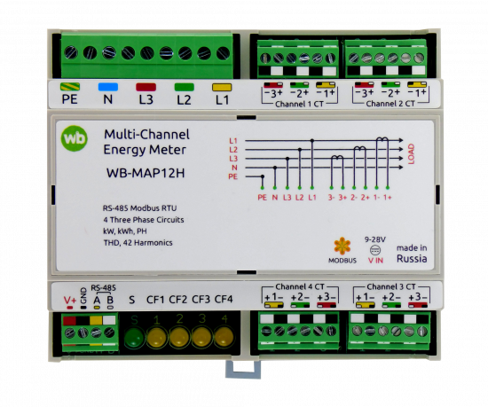
WB-MAP12 is a multichannel electricity meter(meter of electrical network parameters) designed for energy management and power quality monitoring. The WB-MAP12 meter is ideal for process electricity metering in apartment buildings and office buildings, for consumer monitoring in data centers and smart offices.
The use of external plug-in current transformers allows system installation without disconnecting the energy consumers.
For active energy meter provides accuracy class 0.5 S. For reactive energy - accuracy class is 1.
Modifications
| Type | |
|---|---|
| WB-MAP12H | Model with the measurement of the coefficients of the harmonics of current and voltage |
| WB-MAP12 | Model without measuring current and voltage harmonics |
Technical parameters
Measured parameters
For a full list of measured parameters see page Power Meter WB-MAP12H Measuring Parameters
Harmonic amplitudes and the current and total harmonic distortion factor (THD) are measured only in models with index "H".
Characteristics
| Parameter | value |
|---|---|
| power supply | |
| Supply voltage | 9 V — 28 V DC(interface part)
50 V — 250 V AC (measuring part) |
| Maximum power consumption | 1.3 Вт |
| The average power consumption | 0.9 Вт |
| Terminals and wire section | |
| The recommended wire cross section with NSUI, mm2 | 0,75 — 1 (2,5 for power inputs) |
| The length of the standard NSVE sleeve, mm | 8 |
| Torque of screws, N∙m | 0,2 (0,4 for power inputs) |
| Measurement channels | |
| Number of channels | 12 single-phase or 4 three-phase |
| Analyzed harmonics of voltage and current frequency | 1 — 42 |
| Control | |
| control interface | RS-485 |
| Interface isolation | Galvanically isolated from the measuring circuits |
| Communication protocol | Modbus RTU, address is set by software, factory settings are indicated on the label |
| The parameters of the RS-485 interface |
The default speed of 9600 bps; data bits 8; parity N; stop bits 2; the interface Parameters can be configured programmatically:
|
| Ready for operation after powering on | 1 c |
| Dimensions | |
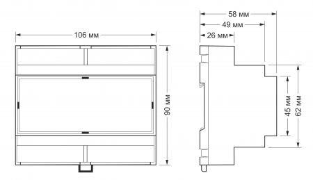
| Dimensions | 106,25 x 90,2 x 57,5 mm |
| Operating conditions | |
| Air temperature | -40°С to +80°С |
| Relative humidity up to | 98%, without condensation |
Meter overall dimensions
Counter power supply
The WB-MAP12(H) counter can be powered from any of the connected phases. For data exchange via Modbus to the controller, you must also apply power to the connector the front end. It is possible to power the meter only from the interface part. In this case, the AC parameters are not measured (the voltage across all channels will be displayed as 0 V), but the current values obtained from the current transformers will be measured correctly.
Накопленные значения энергии сохраняются при отключении питания счетчика.
Работа при провалах и прерываниях напряжения
Замер энергии прекращается при напряжении меньше 180 вольт (провал или прерывание напряжения), порог задается в одном из Modbus-регистров счетчика.
Обмен данными
На физическом уровне модуль подключается через интерфейс RS-485. Для управления счетчиком используется протокол Modbus RTU. В устройствах Wirenboard данные Modbus передаются по линиям связи RS-485. Подробнее смотрите страницу Протокол Modbus. Modbus-адрес счетчика задается на заводе и нанесен на наклейке. Адрес может быть изменен программно. Подробности смотрите в разделе Управление по Modbus.
WB-MAP3H Power Meter Connection
Настройка
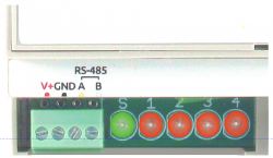
Индикация
Счетчик имеет 5 светодиодных индикаторов:
- S — зеленый индикатор статуса, мигает при обмене данными по Modbus
- CF1...CF4 — красные индикаторы потребляемой суммарной энергии для каждого из трехфазных каналов (учитывается только активная энергия). Мигание индикаторов означает потребление электроэнергии: 1000 импульсов соответствуют 1 кВт·ч (в прошивке до v.2,1 - 3200 импульсов на 1 кВт·ч).
Представление в web-интерфейсе
Полный список названий параметров, отображаемых в web-интерфейсе приводится на странице Счетчик WB-MAP12H: измеряемые параметры и погрешности, их названия в веб-интерфейсе Wiren Board.
{{#invoke:Template translation|renderTranslatedTemplate|template=Template:Warning|noshift=1}}
При добавлении устройства WB-MAP12 вы можете выбрать один из нескольких шаблонов устройств:
| Шаблон | Модель и назначение |
|---|---|
| WB-MAP12H | Основной шаблон для моделей с измерением коэффициентов гармоник тока и напряжения |
| WB-MAP12H (basic) | Упрощенный шаблон для моделей без измерения коэффициентов гармоник тока и напряжения (нет значений AN, Ifund, N, NN, RN, NP, Pfund, Pharm, S, THD I, THD U, Total AN, Total N, Total Pfund, Total Pharm, Total RN, Total RP, Total S, Total SV, Ufund -- названия см. на странице со списком измеряемых параметров, ссылка выше). |
| WB-MAP12H (+ harmonics) | Расширенный шаблон для моделей с измерением коэффициентов гармоник тока и напряжения (до 15 гармоники по току и до 7 гармоники по напряжению) |
| WB-MAP12H (+ all harmonics) | Полный шаблон для моделей с измерением коэффициентов гармоник тока и напряжения (до 42 гармоники по току и по напряжению) |
| WB-MAP12H (basic div2) | Упрощенный шаблон для моделей без измерения коэффициентов гармоник тока и напряжения с вводами, рассчитанными на токи > 65А |
| WB-MAP12E | Шаблон для модели, поддерживающей измерения просадки тока и напряжения (модель в разработке) |
Описание Modbus-регистров
Счетчик поддерживает большое количество Modbus-регистров, которые хранят значения измеряемых и вычисляемых величин, а также регистры управления счетчиком.
Таблицу регистров, описывающих измеряемые величины, можно найти на странице Таблица Modbus-регистров измеряемых и вычисляемых величин.
Таблица управляющих регистров приведена на странице Многоканальный счётчик электроэнергии WB-MAP12H: таблица управляющих Modbus-регистров.
Изображения и чертежи устройства
По ссылкам ниже вы можете скачать изображения и чертежи устройства WB-MAP12H.
Corel Draw 2018: WB-MAP12H.cdr.zip
Corel Draw PDF: WB-MAP12H.cdr.pdf
Autocad 2013 DXF: Мы еще не подготовили чертеж этого устройства. Вы можете запросить чертеж устройства "Многоканальный счётчик электроэнергии WB-MAP12H" на портале техподдержки Wiren Board (необходима регистрация).


