|
|
| Строка 10: |
Строка 10: |
| !Features | | !Features |
| !Firmware version | | !Firmware version |
| |-
| |
| |6x
| |
| |12.2018
| |
| |Inscription r.6.5 on the bottom side of the board, the version in the interface
| |
| |
| |
| *Radiomodule is missing
| |
| *SIM card 1 is located in the lower left corner.
| |
| *Allowable supply voltage increased up to 48V.
| |
| * Power UVLO (6,9-7,7В)
| |
|
| |
| |6x
| |
| |-
| |
| |6.4.1
| |
| |10.2018
| |
| |Inscription r.6.4.1 on the bottom side of the board, the version in the interface
| |
| |
| |
|
| |
| |6.4.1
| |
| |-
| |
| |6.4
| |
| |09.2018
| |
| |Inscription r.6.4 on the bottom side of the Board, the version in the interface
| |
| |
| |
| * New USB-UART chip supporting standard CDC class, on [[WB Debug Console/en| Debug Console]]
| |
| * USB port protection of the debug console from ESD
| |
| * Detachable screw terminals
| |
| * Removed indication modem (NETLIGHT) for the led near the antenna of GSM
| |
| * Fixed bug [[WB 6: Errata/en|0630001]]
| |
| |6.4
| |
| |-
| |
| |6.3
| |
| |02.2018
| |
| |Inscription Wiren Board 6 r.6.3 on the bottom side of the board.
| |
|
| |
|
| |- | | |- |
Версия 18:46, 28 июня 2019
The definition of the revision
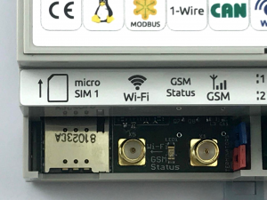
Wiren Board rev.6.5 controller. Micro SIM 1 slot was moved to the front row of terminals
In the latest firmware versions, revision can be viewed in the web interface of the controller, Devices => System, channel system/HW Revision. Programmatical determination of the revision of the controller is possible via MQTT. If there is no such section in the interface, the controller can be identified by marking on the bottom side of the board (under the cover on the side of the DIN rail).
Wiren Board 6 revisions
| Revision
|
Release date
|
Identification
|
Features
|
Firmware version
|
| 6.5
|
12.2018
|
Надпись r.6.5 на нижней стороне платы, версия в интерфейсе
|
- Отсутствие радиомодуля
- Сим карта №1 расположена в левом нижнем углу.
- Увеличено допустимое напряжение питания - до 48В.
- UVLO по питанию (6,9-7,7В)
|
6x
|
| 6.4.1
|
10.2018
|
Надпись r.6.4.1 на нижней стороне платы, версия в интерфейсе
|
|
6x
|
| 6.4
|
09.2018
|
Надпись r.6.4 на нижней стороне платы, версия в интерфейсе
|
- Новый чип USB-UART, поддерживающий стандартный класс CDC, на отладочной консоли
- Защита USB-порта отладочной консоли от ESD
- Разъёмные вертикальные винтовые клеммники
- Выведена индикация модема (NETLIGHT) на светодиод рядом с антенной GSM
- Исправлена ошибка 0630001
|
6x
|
| 6.3
|
02.2018
|
Надпись Wiren Board 6 r.6.3 на нижней стороне печатной платы.
|
|
61
|
6x
|
Differences between Wiren Board 6 and Wiren Board 5
| Overall change
|
Added
|
Removed
|
- Other processor - i.MX 287 was replaced by i.MX 6ULL. Now it is 800MHz Cortex A7 with mathematical coprocessor.
- Increased the RAM from 128 to 512MB
- Changed connectors for expansion modules. On the base Board connectors type "mom", added the key on the headscarves modules.
- The connector for the backup power modules has been changed.
Expansion modules and backup power for Wiren Board 5 is not suitable for Wiren Board 6.
|
- Third expansion connector for modules that do not require external terminals.
- Support for the second SIM card (there is one SIM card in the network at the same time )
- Output short-circuit protection A1-A4
- Temperature sensor on the base Board (sysfs)
- separate RTC
|
|
Wiren Board 5 revisions
| Revision
|
Release date
|
Identification
|
Differences from previous revision
|
Revision in the interface
|
| 5.9
|
|
|
Added separate hardware RTC (non-volatile clock)
|
58
|
| 5.8.1
|
|
|
- Added second Ethernet port
- Changed power supply circuit: input power range extended to 5-28V
- Removed the S/PDIF Toslink connector (it is possible to connect the connector to the pin connector on the Board)
- Removed port for IR transceiver (will be available as extension module)
- Debug console output to micro-USB interface instead of UART
- Added terminal strip for resver power input
Other:
- On request is possible to install a 3G instead of 2G
|
58
|
| 5.6.1
|
|
Inscription Wiren Board 5 r.6.1 on the bottom side of the PCB
|
- The IR port is made small resistors and decoupling from the DC capacitor
|
55
|
| 5.6
|
04.2016
|
Inscription Wiren Board 5 r.6 on the bottom side of the PCB.
No terminal strip R2
|
- Removed R2 terminal strip
- Added VOUT terminal strip - supply voltage output
- Added jumpers to enable terminating resistors on RS-485/CAN lines
- Moved the debug UART to USB connector
- Stability is improved in the firmware recovery mode via microUSB
- Mode is activated by the button flashing the FW, instead of the jumper
- The power from the side I/O modules is not removed when the device is rebooted by the watchdog timer
- Added MOD3 connector to connect mezzanine display module
- Added support for a second USB-host in the configuration without Wi-Fi (available on request)
|
55
|
| 5.3
|
11.2015
|
Inscription Wiren Board 5 r.3 on the bottom side of the PCB.
Terminals R1 and R2 presence
|
|
52
|
Differences between Wiren Board 5 and Wiren Board 4
| Overall change
|
Added
|
Removed
|
- Another processor - IMX233 was replaced by IMX287. The new processor is fully software compatible with the previous one.
- Increased the RAM from 64 to 128MB
|
- Bluetooth low energy (BLE)
- can port
- CIR (infrared port)
- S/PDIF (digital audio)
- connector for two extension modules
- connector for side I/O modules.
|
- 3.5 mm audio Jack (stereo)
- RS-485 isolated (available as extension module))
- Separate inputs for dry contacts (connection to universal ad inputs is possible, extension module is also available)
- Relay (extension module and I/O modules available))
- Charging Li-Ion battery (available as an option)
|


