WB-MAI2-mini/CC 4-20mA Modbus Analog Inputs/en: различия между версиями
(Новая страница: «== Description of Modbus registers == All Modbus registers of the device are divided into 2 groups: * General registers that define device parameters * Registers…») |
FuzzyBot (обсуждение | вклад) (Часть переводимой страницы WB-MAI2-mini/CC.) Метки: правка с мобильного устройства правка из мобильной версии |
||
| (не показано 9 промежуточных версий 2 участников) | |||
| Строка 85: | Строка 85: | ||
* Registers of measured values | * Registers of measured values | ||
=== | === General registers === | ||
{| | {| border="1" class="wikitable" style="text-align:center" | ||
! | !Register/ address | ||
! | !type | ||
! | !read-write | ||
! | !default | ||
! | !format | ||
! | !purpose | ||
|- | |- | ||
|104-105 || input || R || || 32-bit unsigned int | | 104-105 || input || R|| || 32-bit unsigned int || uptime counter in seconds | ||
|| | |||
|- | |- | ||
| 110 || holding || RW || 96 || | | 110 || holding || RW|| 96 || baud rate / 100 || RS-485 port speed, '''divided by 100'''. Permissible speeds: 1200, 2400, 4800, 9600, 19200, 38400, 57600, 115200 <br>([[UART_Communication_Settings/en|configure RS-485 communication parameters for Wiren Board Modbus devices]]) | ||
|- | |- | ||
| 111 || holding || RW || 0 || || | | 111 || holding || RW|| 0 || || configure the RS-485 port parity bit. Valid values: 0 - no parity bit (none), 1 - odd (odd), 2 - even (even) | ||
|- | |- | ||
| 112 || holding || RW || 2 || || | | 112 || holding || RW|| 2 || || number of stop bits of RS-485 port. Valid values: 1, 2 | ||
|- | |- | ||
| 120 (0x78) || holding || RW || 0 || | | 120 (0x78) || holding || RW|| 0 || 0 || write to the register causes a stateless | ||
reboot of the module | |||
|- | |- | ||
| 121 (0x79) || input || R || - || | | 121 (0x79) || input || R || - || mV || current supply voltage of the module | ||
|- | |- | ||
| 128 (0x80) || holding || RW || | | 128 (0x80) || holding || RW || written on the label on the case || || Modbus address of the device | ||
|- | |- | ||
| 200-206 || input || R || {'M','A','I','2','C','C'} || | | 200-206 || input || R || {'M','A','I','2','C','C'} | | | device signature | ||
|- | |- | ||
| 220-241 || input || R || || | | 220-241 || input || R | | | | _date__ _time__|| firmware build date | ||
|- | |- | ||
| 250-269 || input || R || | | | 250-269 || input || R | | | / string, null-terminated || firmware version | ||
|- | |- | ||
| 270-271 || input || R || || | | 270-271 || input || R|| || 32-bit unsigned int || unique identifier (S/N) | ||
|- | |- | ||
|} | |} | ||
=== | === Registers containing the values of the measured values === | ||
{| | {| border="1" class="wikitable" style="text-align:center; width:1000px;" | ||
! | !Register / address (hex) | ||
! | !Type | ||
! | !Digit capacity | ||
! | !Byte order | ||
! | !Format | ||
! | !Multiplier | ||
! | !Parameter | ||
! | !Purpose | ||
! | !Unit | ||
|- | |- | ||
| 246 | | 246 || input || s16 || big endian || (value) || 3.125 e-02 || Current input 1 (mA) | | / channel Current 1 || mA | ||
|- | |- | ||
| 247 | | 247 || input || s16 || big endian || (value) || 3.125 e-02 || Current input 2 (mA) | | / channel Current 2 || mA | ||
|- | |- | ||
|} | |} | ||
== | == Images and drawings of the device == | ||
{{Wbincludes:WBPicturesNoDrawing|1}} | {{Wbincludes:WBPicturesNoDrawing|1}} | ||
<!--{{Wbincludes:WBPictures|1}}--> | <!--{{Wbincludes:WBPictures|1}}--> | ||
Текущая версия на 21:34, 20 апреля 2021
Purpose
WB-MAI2-mini/CC is a compact analog input module designed to measure current signal 4..20 mA via two independent channels. The module is controlled from the controller or PC via RS-485 bus by Modbus commands.
Specifications
| Parameter | Value |
|---|---|
| Power | |
| Supply voltage | 9 V – 28 V |
| measurement Channels | |
| Number of channels | 2 |
| Current measurement | 0 – 20 mA |
| Input impedance | A 49.9 Ohm |
| Current measurement error | ±1% |
| Control | |
| Management interface | RS-485 |
| Interface isolation | no |
| Communication protocol | Modbus RTU, the address is set by software, factory settings are indicated on the label |
| RS-485 interface parameters | Default speed of 9600 bps; data bits 8; parity N; stop bits 2.
Interface parameters can be configured programmatically:
|
| Ready for operation after power supply | 1 c |
| dimensions | |
| Size | 57 x 18 x 14 mm |
| operating Conditions | |
| Air temperature | |
| Relative humidity | up to 98%, without condensation |
Connection diagrams
The module is made in a compact housing and is designed for installation in solder boxes and cable channels.
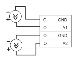
The figure shows the connection diagram of sensors with a current output of 0-20 mA (4-20 mA). The internal resistance of the inputs — 49.9 Ohms.
Presentation in the web interface
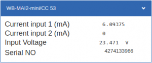
The web interface for the module displays current values (controls "Current input 1 (mA)" and "Current input 2 (mA)"), supply voltage and serial number. The "CC" in the device name indicates that it supports two current inputs (Current).
Description of Modbus registers
All Modbus registers of the device are divided into 2 groups:
- General registers that define device parameters
- Registers of measured values
General registers
| Register/ address | type | read-write | default | format | purpose |
|---|---|---|---|---|---|
| 104-105 | input | R | 32-bit unsigned int | uptime counter in seconds | |
| 110 | holding | RW | 96 | baud rate / 100 | RS-485 port speed, divided by 100. Permissible speeds: 1200, 2400, 4800, 9600, 19200, 38400, 57600, 115200 (configure RS-485 communication parameters for Wiren Board Modbus devices) |
| 111 | holding | RW | 0 | configure the RS-485 port parity bit. Valid values: 0 - no parity bit (none), 1 - odd (odd), 2 - even (even) | |
| 112 | holding | RW | 2 | number of stop bits of RS-485 port. Valid values: 1, 2 | |
| 120 (0x78) | holding | RW | 0 | 0 | write to the register causes a stateless
reboot of the module |
| 121 (0x79) | input | R | - | mV | current supply voltage of the module |
| 128 (0x80) | holding | RW | written on the label on the case | Modbus address of the device | |
| 200-206 | input | R | | | device signature | ||
| 220-241 | input | | | | _date__ _time__ | firmware build date | ||
| 250-269 | input | | | / string, null-terminated | firmware version | ||
| 270-271 | input | R | 32-bit unsigned int | unique identifier (S/N) |
Registers containing the values of the measured values
| Register / address (hex) | Type | Digit capacity | Byte order | Format | Multiplier | Parameter | Purpose | Unit |
|---|---|---|---|---|---|---|---|---|
| 246 | input | s16 | big endian | (value) | 3.125 e-02 | | / channel Current 1 | mA | |
| 247 | input | s16 | big endian | (value) | 3.125 e-02 | | / channel Current 2 | mA |
Images and drawings of the device
По ссылкам ниже вы можете скачать изображения и чертежи устройства WB-MAI2-mini-CC.
Corel Draw 2018: WB-MAI2-mini_СС.cdr.zip
Corel Draw PDF: WB-MAI2-mini_СС.cdr.pdf
Autocad 2013 DXF: Мы еще не подготовили чертеж этого устройства. Вы можете запросить чертеж устройства "Analog input module WB-MAI2-mini/CC" на портале техподдержки Wiren Board (необходима регистрация).


