WB-MIO
Buy WB-MIO in the online store Buy WB-MIO-E online store
Purpose
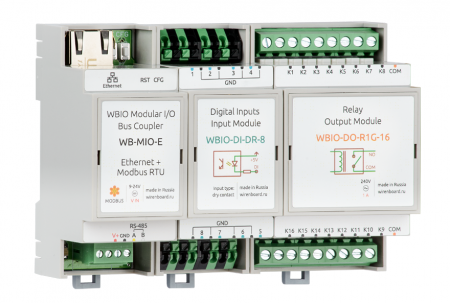
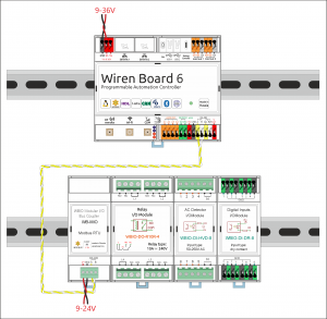
WB-MIO and WB-MIO-E interface converters are designed for remote connection of devices "WBIO" (I/O modules) via Modbus RS-485 or Ethernet (in WB-MIO-E). Allow, if necessary, to separate the I/O modules from the Wiren Board controller and transfer to another DIN rail or to another shield. It also allows you to use I/O modules as a separate device with controllers from other manufacturers.
Interface conversion
There are three modifications of WB interface converters: WB-MIO, WB-MIO-E and WB-MGE. The table below shows which interface each module converts to.
| Model | From | To | |||
|---|---|---|---|---|---|
| RS-485
(Modbus) |
Ethernet
(IP) |
WBIO | RS-485
(Modbus) |
Ethernet
(IP) | |
| WB-MIO | + | + | |||
| WB-MIO-E | + | + | + | ||
| WB-MGE | + | + | + | + | |
Technical specifications
| Option | Value |
|---|---|
| Power | |
| Supply voltage front-end | 9 V — 24 V DC |
| Power consumption |
0.85 W |
| Terminals and wire section | |
| Recommended wire cross-section, mm2 | 0,75 — 1 |
| Length of the standard sleeve, mm | 8 |
| Torque of screws, N∙m | 0,2 |
| Communication | |
| Communication protocol | Modbus RTU, WBIO |
| Interfaces |
|
| RS-485 interface parameters | set programmatically, by default:
speed 9600 bps; data bits 8; parity N; stop bits 2;
|
| dimensions | |
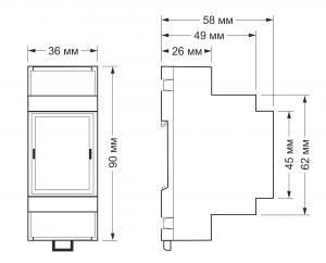
| Size | 2 DIN; 36,3x90,2x57,5 mm |
| Operating conditions | |
| Air temperature | -40°C to +80°C |
| Relative humidity | up to 92%, no condensation |
Modifications
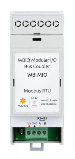
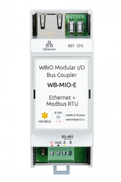
Interface module WB-MIO is available in two versions, characterized by the presence of Ethernet interface: WB-MIO and WB-MIO-E.
| Modification | RS-485 interface | Ethernet interface |
|---|---|---|
| WB-MIO | yes | no |
| WB-MIO-E | yes | yes |
RS-485 interface connection
WB-MIO(-E) is connected to the controller via connectors A and B RS-485. If power is supplied from a separate power supply, the ground of the controller and the power supply must be combined.
See article RS-485:Physical connection.
The WB-MIO module is a peripheral device (slave) in the Modbus network.
Ethernet connection
Modification WB-MIO-E with Ethernet interface is connected to the local Ethernet network: to the router port or directly to one of the Ethernet ports of the programmable Wiren Board controller.
WB-MIO-E power is supplied to V+ and GND terminals. Module WB-MIO-E does NOT support PoE.
On the default Ethernet network, WB-MIO-E' has a static IP address of 192.168.0.7. To work with the Wiren Board controller software, the Ethernet part of the WB-MIO-E module must be configured in "TCP Server" mode. Detailed instructions on how to configure the Ethernet part of WB-MIO-E can be found on configuring Ethenet interfaces and connecting WB-MIO-E and WB-MGE modules].
Connection of I/O modules
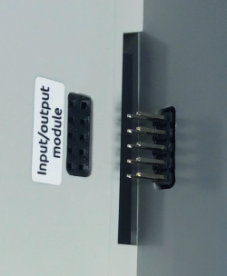
I/O modules are connected to the WB-MIO by connecting to it from the side (entering the side connector).
Up to 9 modules can be connected in series: up to 4 input modules (type "I"), up to 4 output and I / o modules (type "O" and "IO"), one WBIO-AI-DV-12 module. The module type determines the type of module addressing by the controller on the side connector bus. Addresses are distributed in sequence. Up to 4 modules can be connected in any sequence. With a larger number, you should connect one type first, then another.
Configuration in the web interface
[[Драйвер wb-mqtt-serial/en|Wb-mqtt-serial driver] is responsible for working with WB-MIO(-E) connected via RS-485 or Ethernet in the Wiren Board controllers.
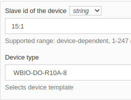
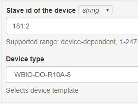
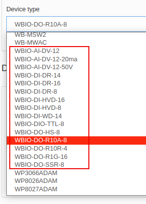
To connect WBIO modules via WB-MIO, go to the web interface of the controller, to the Configs tab, select the /etc/wb-mqtt-serial file.conf. Next, you need to add a new Serial device to the required port. In the field "Slave id of the device" specify the address of the WB-MIO device, add a colon, then number on the count of connected I/o module in a row.
For example, if we have only one module connected to WB-MIO, the string "Slave id of the device" for this module will look like this: 15:1. Where 15 is the Modbus address of WB-MIO and 1 is the I/O module account number. In the "Device type" field, select the type of the connected module. Template names for them start with "WBIO-..."
Modbus Control
A map of the WB-MIO and WB-MIO-E Modbus registers can be found on WB-MIO-Modbus-Registers/en. For more information on working with Modbus devices, see Modbus Protocol
Images and drawings of the device
По ссылкам ниже вы можете скачать изображения и чертежи устройства WB-MIO.
Corel Draw 2018: WB-MIO.cdr.zip
Corel Draw PDF: WB-MIO.cdr.pdf
Autocad 2013 DXF: Мы еще не подготовили чертеж этого устройства. Вы можете запросить чертеж устройства "Bus coupler WB-MIO" на портале техподдержки Wiren Board (необходима регистрация).
По ссылкам ниже вы можете скачать изображения и чертежи устройства WB-MIO-E.
Corel Draw 2018: WB-MIO-E.cdr.zip
Corel Draw PDF: WB-MIO-E.cdr.pdf
Autocad 2013 DXF: WB-MIO-E.dxf.zip
Autocad PDF: WB-MIO-E.pdf
