WB-MR6F Modbus Relay Module
Purpose
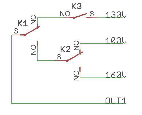
Specialized two-channel relay module WB-MR6F is designed for step load control, for example, for three-stage speed control of convector fans.
Incorrect software settings and mechanical faults of the relay can not cause a short circuit of the input voltages Vx between themselves because of the device design.
The channels are designed for a 3A load.
Outputs
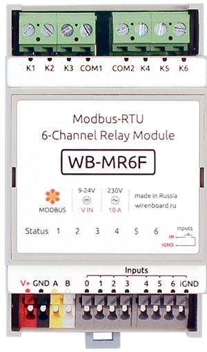
The module has 6 HF32F relays (Datasheet).
Each of the two channels of the module consists of two rocker relays and one relay with normally open contacts. Depending on the position of the relay, each of the OUTx outputs is either connected to one of the three Vx inputs or disconnected from the Vx inputs (off state).
The module can be timer enabled safe mode, which at the termination of the data exchange through Modbus module disables all the relays after a specified time.
The table below lists the specifications and conditions of use of the WB-MR6F relay module. Each output of the module is protected from arcing when the varistor closes/opens. Depending on the Modbus register settings, the status of the inputs can be resumed after a power interruption (see Relay operation mode in case of power failure).
Inputs
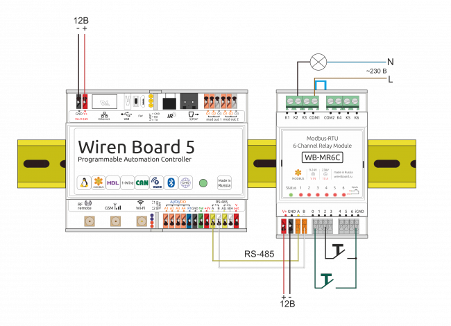
The inputs of the modules WB-MR6F displayed on the screwless terminal blocks. Inputs are organized on the principle of dry contact. Buttons or switches are connected between the corresponding inputs and iGND inputs. There is a special input for disconnecting all relays of the module at the same time.
Each input controls the state of the corresponding relay.
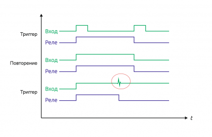
The inputs have two modes of operation: trigger mode (for control with buttons) and repeat mode (for control with switches). In the trigger mode, to change the state of the relay, it is enough to close and open the input once. The change of state occurs on the rising edge (that is, when the circuit). In the repeat mode, the relay state is determined by the input state: the input is closed — the relay is on, open — off. Details about the mode switching written in Modbus Management Of Relay Modules.
It is not recommended to use switches (e.g. buttons with fixation) in the trigger mode of inputs. Input interference may be perceived as a short release/push of the button and the relay status will change, although the switch will remain closed.
Technical specifications
Our detailed article in russian on habr.com about the choice of relay parameters for the switched load: https://habr.com/ru/company/wirenboard/blog/422197/
| Parameter | Value |
|---|---|
| Power | |
| Supply voltage | 9 — 28 V DC |
| Power consumption |
|
| Outputs | |
| Number of outputs | 2 |
| Output type | Mechanical relay contacts |
| Contact configuration | Four-position, normally open (States: Open, V1, V2, V3) |
| Output configuration | - |
| Maximum switching voltage, AC | 250 V |
| Maximum switching voltage, DC | 30 Volts |
| Maximum switching current per channel | 3 A |
| Contact resistance | < 100 milliohms |
| Voltage isolation between the controller and the output | 1500 V (RMS value) |
| Term life: | 100 000 switchings for 3 A/230V AC load |
| Inputs | |
| Number of inputs (Inputs 0—6) | 7 (6+1) Input 0 disconnects all relays of the module simultaneously |
| Input type | "Dry contact", group insulation.
The input voltage is ~4.5 V. Current closing input ~2mA. |
| Functions |
|
| Control | |
| Management interface | RS-485 |
| Interface isolation | Uninsulated |
| Communication protocol | Modbus RTU, address is set by software, factory settings are indicated on the label |
| RS-485 interface parameters | set programmatically (see register Card); default: speed — 9600 bit/s; data — 8 bit; parity bit — none (N); stop bits — 2 |
| Ready for operation after power supply | ~0.03 c |
| dimensions | |
| Width, DIN units | 3 |
| Overall dimensions (l x W x h) | 53.3 x 56.3 x 57.5 mm |
| Display | |
| Power and data exchange indication | Green Status led (located under the surface of the top sticker) |
| Relay channel status indication | Red-orange LEDs 1 — 6 (located under the surface of the top sticker) |
| operating Conditions | |
| Air temperature | |
| Relative humidity | Up to 92%, no condensation |
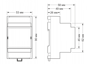
= = Module dimensions ==
The overall dimensions of the module are 53.3 x 90.2 x 57.5 mm (L x W x H), see features.
Data exchange
At the physical level, the module is connected via RS-485 interface. Modbus RTU Protocol is used to control the WB-MR6F. In Wiren Board devices, Modbus data is transmitted over RS-485 communication lines. See the Modbus Protocol page for details. Modbus-address of the device is set at the factory and marked on the label. The address can be changed programmatically. Details refer to the Modbus control.
Installation
The relay module is mounted on a standard 35 mm wide DIN rail and occupies a width of 3 DIN modules.
The screw-free terminal blocks on the relay board are used to connect power lines, control (RS-485) and input contacts. When using handpieces for installation of wires in screw-free clamps, it is necessary that the diameter of the insulated cuffs does not exceed 3.6 mm, the wire section — 0.75 mm2, and the length of the conductive sleeve — 5-6 mm. Screw clamps accept wire section 2.5—4 mm2. The wire section must correspond to the switched load.
When connecting the switching devices to the relay contacts, it is important not to exceed the recommended current of 3 A.
The current flowing when the button or switch is closed is small, so the type of button or switch can be any. Despite the built-in protection against rattle, choose quality buttons and switches to avoid false alarms due to bad contacts.
If the device is the last one on the RS-485 line, a 120 Ohm resistor-terminator must be installed between its inputs A and B. Practice shows that in the case of bench tests with a small length of the RS-485 line and a small number of terminator devices on the last device in the line can not be installed.
Модуль необходимо устанавливать таким образом, чтобы удовлетворять требованиям электробезопасности и не допускать случайного касания контактов, находящихся под высоким напряжением. Модуль должен эксплуатироваться при рекомендованных условиях окружающей среды.
Управление модулем через web-интерфейс Wiren Board
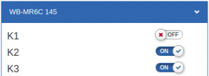
Для устройства используется шаблон WB-MR6C. Каждому каналу соответствует три переключателя, управляющими тремя реле в группе: K1, K2, K3 относятся к первому каналу, K4, K5, K6 - ко второму.
Соответствие реле положению выходов:
| K1/
K4 |
K2/
K5 |
K3/
K6 |
OUT1/
OUT2 | |
|---|---|---|---|---|
| OFF | OFF | OFF | Отключен | |
| ON | ||||
| ON | OFF | ON | V1 | |
| OFF | ||||
| ON | ON | ON | V3 | |
| OFF | ||||
| OFF | ON | ON | V2 | |
| OFF |
С помощью виртуальных выключателей в web-интерфейсе K1-K6 можно управлять соответствующими выходами модуля и следить за их состоянием. Если реле будет включено или выключено через внешний вход, это отразится и в web-интерфейсе. Текущее состояние входов показывают флажки Input1 — Input6 (на них нельзя щелкнуть, чтобы изменить состояние). Счетчики нажатий/включений отображаются в полях Input 1 counter – Input 6 counter. Значения счетчиков хранятся в оперативной памяти микроконтроллера модуля реле и обнуляются при выключении/включении питания и сбросе.
Ползунок Safety Timer позволяет задать время отключения (в секундах) всех выходов при отсутствии обмена данными с Wiren Board (0 – таймер безопасности отключен). При возобновлении связи с контроллером выключившиеся реле останутся выключенными. Ползунком удобно управлять с помощью клавиш со стрелками, предварительно сфокусировавшись на нем мышью: перемещение ползунка с помощью мыши не обеспечивает достаточную точность. Таймер безопасности позволяет остановить технологические процессы в случае, если контроль над модулем утрачен (например, перебит кабель RS-485).
Кнопка, подключенная ко входу 0, позволяет отключить все включенные реле модуля одним нажатием. Повторное нажатие включит все реле, которые были включены изначально. Состояние реле хранится в оперативной памяти, поэтому если повторной нажатие кнопки произойдет после перебоя питания, восстановления состояния реле не произойдет. Возможность восстановления состояния реле после перебоя питания описана в разделе Режим работы реле в случае отключении питания.
Режим работы реле в случае отключении питания
В зависимости от значения, записанного в регистр хранения 0x06, после отключения и восстановления питания модуля реле останутся выключенными (если значение — 0, или включатся те, которые были включены до перерыва в питании, если в регистре записано значение 1). Этот функционал появился в модулях с прошивкой, начиная с версии 1.5.3.
Управление по Modbus
Подробно о работе с модулем по протоколу Modbus написано в разделе Управление модулями реле Wirenboard по протоколу Modbus. Там же можно найти карту регистров устройства.
Назад к списку периферийных устройств
Обновление прошивки устройства
Начиная с новых версий микропрограмм устройства поддерживается функционал обновления прошивки (микропрограммы) по протоколу Modbus. Это дает возможность расширять функциональные возможности устройств и устранять ошибки в микропрограммном обеспечении непосредственно на месте монтажа. Подробнее о перепрошивке устройств рассказано в статье Загрузка прошивок на устройства Wiren Board. Список версий прошивок, поддерживающих обновление, а также устройств, для которых эта функция реализована, можно найти в статье Firmware_Changelog.
