WB-MR6F Modbus Relay Module
Purpose
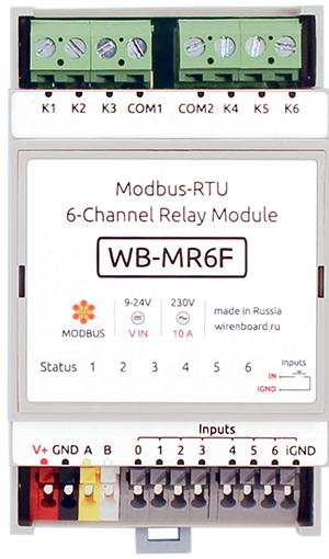
Specialized two-channel relay module WB-MR6F is designed for step load control, for example, for three-stage speed control of convector fans.
Incorrect software settings and mechanical faults of the relay can not cause a short circuit of the input voltages Vx between themselves because of the device design.
The channels are designed for a 3A load.
Outputs
The module has 6 HF32F relays (Datasheet).
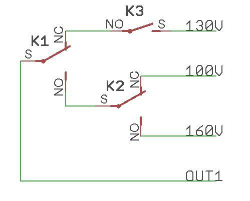
Each of the two channels of the module consists of two rocker relays and one relay with normally open contacts. Depending on the position of the relay, each of the OUTx outputs is either connected to one of the three Vx inputs or disconnected from the Vx inputs (off state).
The module can be timer enabled safe mode, which at the termination of the data exchange through Modbus module disables all the relays after a specified time.
The table below lists the specifications and conditions of use of the WB-MR6F relay module. Each output of the module is protected from arcing when the varistor closes/opens. Depending on the Modbus register settings, the status of the inputs can be resumed after a power interruption (see Relay operation mode in case of power failure).
Inputs
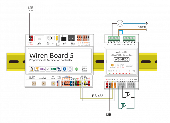
The inputs of the modules WB-MR6F displayed on the screwless terminal blocks. Inputs are organized on the principle of dry contact. Buttons or switches are connected between the corresponding inputs and iGND inputs. There is a special input for disconnecting all relays of the module at the same time.
Each input controls the state of the corresponding relay.
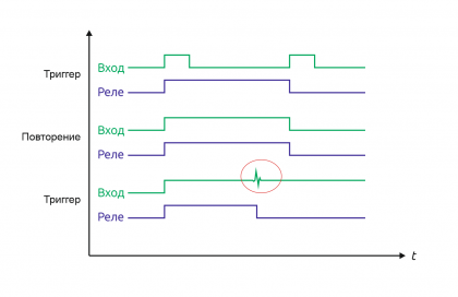
The inputs have two modes of operation: trigger mode (for control with buttons) and repeat mode (for control with switches). In the trigger mode, to change the state of the relay, it is enough to close and open the input once. The change of state occurs on the rising edge (that is, when the circuit). In the repeat mode, the relay state is determined by the input state: the input is closed — the relay is on, open — off. Details about the mode switching written in Relay Module Modbus Management.
It is not recommended to use switches (e.g. buttons with fixation) in the trigger mode of inputs. Input interference may be perceived as a short release/push of the button and the relay status will change, although the switch will remain closed.
Technical specifications
Our detailed article in russian on habr.com about the choice of relay parameters for the switched load: https://habr.com/ru/company/wirenboard/blog/422197/
| Parameter | Value |
|---|---|
| Power | |
| Supply voltage | 9 — 28 V DC |
| Power consumption |
|
| Outputs | |
| Number of outputs | 2 |
| Output type | Mechanical relay contacts |
| Contact configuration | Four-position, normally open (States: Open, V1, V2, V3) |
| Output configuration | - |
| Maximum switching voltage, AC | 250 V |
| Maximum switching voltage, DC | 30 Volts |
| Maximum switching current per channel | 3 A |
| Contact resistance | < 100 milliohms |
| Voltage isolation between the controller and the output | 1500 V (RMS value) |
| Term life: | 100 000 switchings for 3 A/230V AC load |
| Inputs | |
| Number of inputs (Inputs 0—6) | 7 (6+1) Input 0 disconnects all relays of the module simultaneously |
| Input type | "Dry contact", group insulation.
The input voltage is ~4.5 V. Current closing input ~2mA. |
| Functions |
|
| Control | |
| Management interface | RS-485 |
| Interface isolation | Uninsulated |
| Communication protocol | Modbus RTU, address is set by software, factory settings are indicated on the label |
| RS-485 interface parameters | set programmatically (see register Card); default: speed — 9600 bit/s; data — 8 bit; parity bit — none (N); stop bits — 2 |
| Ready for operation after power supply | ~0.03 c |
| dimensions | |
| Width, DIN units | 3 |
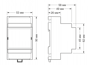
| Overall dimensions (l x W x h) | 53.3 x 56.3 x 57.5 mm |
| Display | |
| Power and data exchange indication | Green Status led (located under the surface of the top sticker) |
| Relay channel status indication | Red-orange LEDs 1 — 6 (located under the surface of the top sticker) |
| operating Conditions | |
| Air temperature | |
| Relative humidity | Up to 92%, no condensation |
= = Module dimensions ==
The overall dimensions of the module are 53.3 x 90.2 x 57.5 mm (L x W x H), see features.
Data exchange
At the physical level, the module is connected via RS-485 interface. Modbus RTU Protocol is used to control the WB-MR6F. In Wiren Board devices, Modbus data is transmitted over RS-485 communication lines. See the Modbus Protocol page for details. Modbus-address of the device is set at the factory and marked on the label. The address can be changed programmatically. Details refer to the Modbus control.
Installation
The relay module is mounted on a standard 35 mm wide DIN rail and occupies a width of 3 DIN modules.
The screw-free terminal blocks on the relay board are used to connect power lines, control (RS-485) and input contacts. When using handpieces for installation of wires in screw-free clamps, it is necessary that the diameter of the insulated cuffs does not exceed 3.6 mm, the wire section — 0.75 mm2, and the length of the conductive sleeve — 5-6 mm. Screw clamps accept wire section 2.5—4 mm2. The wire section must correspond to the switched load.
When connecting the switching devices to the relay contacts, it is important not to exceed the recommended current of 3 A.
The current flowing when the button or switch is closed is small, so the type of button or switch can be any. Despite the built-in protection against rattle, choose quality buttons and switches to avoid false alarms due to bad contacts.
If the device is the last one on the RS-485 line, a 120 Ohm resistor-terminator must be installed between its inputs A and B. Practice shows that in case of bench tests with a small length of the RS-485 line and a small number of terminator devices, it's not necessary to install terminator on the last device in the line.
The module must be installed to meet the requirements of electrical safety and to prevent accidental contact of contacts under high voltage. The module must be operated under recommended environmental conditions.
Control of the module via the Wiren Board web interface
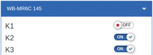
The device uses the WB-MR6F template. Each channel corresponds to three switches that control three relays in the group: K1, K2, K3 belong to the first channel, K4, K5, K6 - to the second.
The relay corresponds to the position of the outputs:
| K1/
K4 |
K2/
K5 |
K3/
K6 |
OUT1/
OUT2 | |
|---|---|---|---|---|
| OFF | OFF | OFF | OFF | |
| ON | ||||
| ON | OFF | ON | V1 | |
| OFF | ||||
| ON | ON | ON | V3 | |
| OFF | ||||
| OFF | ON | ON | V2 | |
| OFF |
Using virtual switches K1-K6 in the web-interface, you can control the corresponding outputs of the module and monitor their status. If the relay is turned on or off via the external input, it will be reflected in the web-interface. The current state of the inputs is indicated by the Input1 — Input6 checkboxes (they cannot be clicked to change the state). Press/enable counters are displayed in the Input 1 counter – Input 6 counter fields. The meter values are stored in the memory of the relay module microcontroller and are reset when the power is turned on/off and reset.
The Safety Timer slider allows you to set the shutdown time (in seconds) of all outputs when there is no communication with the Wiren Board (0 – the safety timer is disabled). When communication with the controller is resumed, the switched-off relays will remain switched off. The slider is easy to control with the arrow keys, previously focusing on it with the mouse: moving the slider with the mouse does not provide sufficient accuracy. The safety timer allows stopping technological processes in case the control over the module is lost (for example, the RS-485 cable is broken).
A button connected to input 0 allows you to turn off all the relays included in the module with a single press. Pressing again will turn on all the relays that were switched on initially. The status of the relay is stored in memory, so if you press the button again after a power failure, the restoration of the relay will not happen. The ability to restore relay status after power supply interruption as described in section Relay operation mode in case of power failure.
Relay operation in case of power failure
Depending on the value written to the storage register 0x06, after the power is turned off and restored, the relays will remain off (if the value is 0, or turn on those that were turned on before the power interruption if the register has a value of 1). This feature appeared in the modules with the firmware, starting with version 1.5.3.
Modbus Control
Details of the work with the module via Modbus Protocol is written in Relay Modules Modbus Management . There you can also find a map of the device registers.
Back to peripheral devices list
Device firmware update
Starting with the new firmware versions of the device, the firmware update functionality (firmware) via the Modbus Protocol is supported. This makes it possible to extend the functionality of the devices and eliminate errors in the firmware directly at the installation site. Read more about flashing devices described in the article Download firmware to Wiren Board devices. A list of firmware versions that support the update, as well as devices for which this feature is implemented, can be found in Firmware Changelog.
